Do you have a question about the Agilent Technologies Infinity II 1290 and is the answer not in the manual?
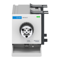
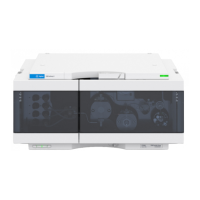
Overview of the Agilent 1290 Infinity II Flexible Pump's capabilities and design.
Key characteristics and functionalities of the Agilent 1290 Infinity II Flexible Pump.
Explanation of how the Agilent 1290 Infinity II Flexible Pump functions.
Details on the different operational modes of the Multi Purpose Valve.
Procedures and concepts for managing leaks and waste in the system.
Guidelines for proper disposal of waste materials.
Environmental and operational conditions needed for the instrument.
Dimensions, weight, power, and other physical properties of the pump.
Key performance metrics including flow, pressure, and accuracy.
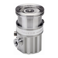
Information regarding the use of magnets within the pump system.
Step-by-step instructions for powering the pump on and off.
Explanation of the different status lights and their meanings.
Recommended procedures for optimal daily use and maintenance.
Guidelines for handling and managing solvents for the pump.
Procedure for configuring channels on the Multi-Channel Gradient Valve.
Understanding and managing system volumes for optimal separation.
Steps to adjust delay volume for improved chromatographic performance.
Techniques and parameters to enhance peak separation and resolution.
How to import and use solvent calibration data for accurate pump control.
Overview of the different user interfaces for system interaction.
Information on using Agilent Lab Advisor for diagnostics and maintenance.
Explanation of how error messages are displayed and handled.
List and explanation of generic error codes applicable to modules.
Specific error codes and troubleshooting for the pump module.
Overview of maintenance procedures and recommended intervals.
Important safety warnings and precautions before performing maintenance.
General description of maintenance tasks that can be performed.
Instructions for cleaning the exterior of the pump module.
Procedure for correctly installing fittings and capillaries.
Steps for removing and reinstalling the module doors.
Detailed steps for replacing the pressure sensor.
Procedure for replacing the inlet weaver assembly.
Instructions for replacing the inlet valve.
Steps for replacing the outlet valve.
Procedure for removing the optional Jet Weaver.
Procedure for installing the optional Jet Weaver.
Instructions for replacing the seal wash pump.
Detailed steps to replace the MCGV.
Method to release an inlet valve that has become stuck.
General procedures and precautions for pump head maintenance.
Step-by-step guide to replace the multi-purpose valve.
Identification of major assemblies and components of the pump.
Diagram and list of all flow path connections in the pump.
Detailed list and diagrams of parts for the pump head assembly.
Specific parts list and diagram for the primary pump head.
Specific parts list and diagram for the secondary pump head.
Parts list for the Multi Purpose Valve.
List of parts related to the module covers.
Contents of the accessory kit for the instrument.
List of tools required for maintenance and repair.
Specific tools and service kits available for the instrument.
General information and listing of all cable types used with the modules.
Details and pinouts for analog signal cables.
Information on remote interface cables for controlling the instrument.
Specifications for CAN and LAN communication cables.
Cable types and connections for interfacing modules with a PC.
Details on USB cables for module connectivity.
Explanation of the instrument's firmware architecture and systems.
Information about the module's connectors and electrical interfaces.
Format and meaning of the instrument's serial number.
Identification of connectors and controls on the rear panel.
Overview of all available communication interfaces for Agilent modules.
Detailed description of CAN, LAN, RS-232C, USB, REMOTE, and Analog interfaces.
How to configure module settings using the DIP switches.
Specific switch settings for boot-resident and forced cold start modes.
Explanation of the EMF feature for proactive maintenance scheduling.
Description of the internal packaging and design of the module.
Initial steps for setting up LAN connectivity for the module.
How to configure IP address, subnet mask, and gateway.
Using the rear panel switch to set initialization and link modes.
Selecting how the module obtains network parameters (Bootp, DHCP, Stored, Default).
How to use DHCP for automatic IP address assignment.
Manually setting LAN speed and duplex modes.
Setting up automatic IP configuration using the BootP protocol.
Configuring network parameters manually via Telnet.
Configuring PC network settings for local connection.
Instructions for installing and setting up control software.
Essential safety precautions, handling of solvents, and operational warnings.
Explanation of safety symbols used on the instrument and in the manual.
Information on WEEE directive, radio interference, and sound emission standards.
Accessing the official Agilent website for product and service information.
| Maximum Pressure (psi) | 18, 850 psi |
|---|---|
| Max Pressure | 1300 bar |
| Pumping Mechanism | Dual-piston, serial flow |
| Solvent Compatibility | Compatible with a wide range of solvents |
| Flow Precision | <0.07% RSD |
| Gradient Composition Range | 0 to 100% |