Technical Information
J1 – IN-OUT
J1 – IN-OUT
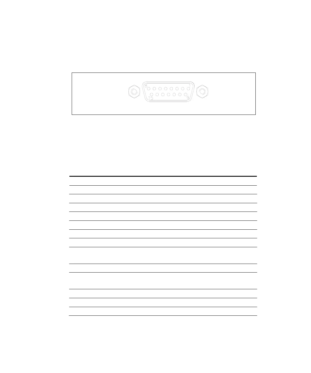
Figure 14 J1 - IN-OUT
This connector carries all the input and output signals for remote
control the TwisTorr 74 FS AG On-board.
It is a 15-pin D type connector; the available signals are detailed in
the table, the following paragraphs describe the signal characteristics
and use.
1 START/STOP (+) IN
2 START/STOP (-) IN
3 INTERLOCK (+) IN
4 INTERLOCK (-) IN
7 SOFT START (+) IN
8 SOFT START (-) IN
MAX
10 NORMAL OUTPUT (Relay)
V
MAX
= 125V I
MAX
= 200mA
OUT
11 PROGRAMMABLE SET POINT (Open collector) OUT
12 NORMAL OUTPUT (Relay)
V
MAX
= 125V I
MAX
= 200mA
OUT
13 FAIL (Open collector) OUT
PROGRAMMABLE ANALOG SIGNAL (+)
15 GROUND PROGRAMMABLE ANALOG SIGNAL (-) OUT
160/192 TwisTorr 74 FS AG On-board Controller User Manual / 87-901-054-01
 Loading...