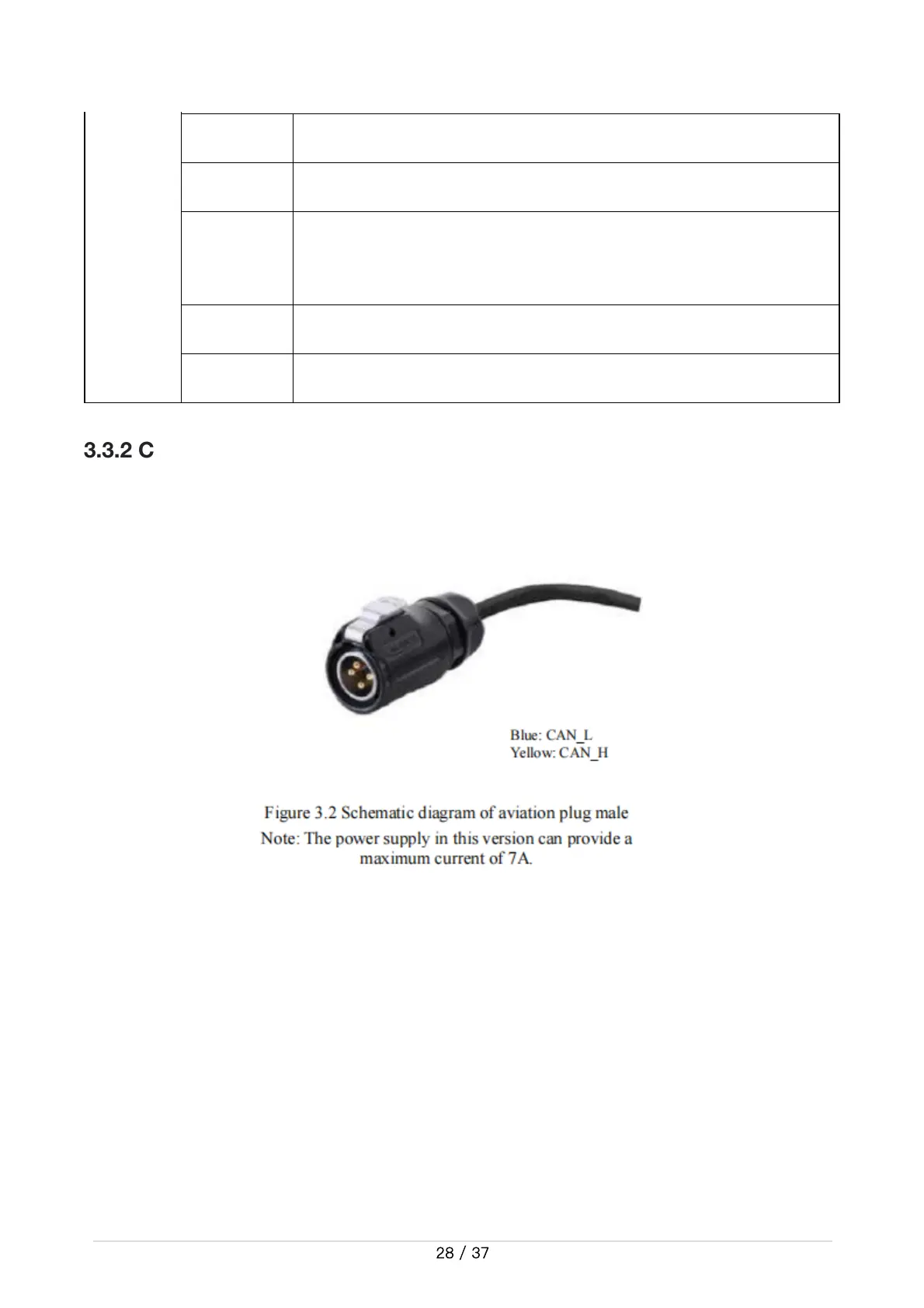
3.3.2CANlineconnection
TRACER MINI provides an aviation plug male as shown in Figure 3.2. For the definition of the line,
please refer to Table 3.2.
3.3.3RealizationofCANcommandcontrol
Start the TRACER MINI mobile robot chassis normally, turn on the FS remote control, and then
switch the control mode to command control, that is, push the SWB mode selection button to the
top, then the TRACER chassis will accept the command from the CAN interface, and the host can
also analyze the current chassis status through the real-time data fed back by the CAN bus. Refer
to the CAN communication protocol for the specific protocol content
bit[2] Whetherthemotorisovercurrent(0:normal1:overcurrent)
bit[3] Reserved
bit[4]
WhethertheCANcommunicationisdisconnected
(0:normal1: disconnected)
bit[6] Reserved
bit[7] Reserved
 Loading...