Electrical Interfaces
AGD301 Product Manual Rev.2.0 Page 47
Each output can be programmed (by a software parameter) to act as a current sourcing output
(up to 300mA) or as a current sinking output (up to 500mA).
The outputs are designed for resistive loads. For inductive loads, an external flyback diode is
required.
Digital outputs specifications:
Digital_Output_Common_Power voltage range is between 5V and 28V.
Maximal load current, per each output:
Sink mode, any Digital_Output_Common_Power voltage: 500 mA
Source mode, at 24V Digital_Output_Common_Power: 300 mA
Source mode, at 5V Digital_Output_Common_Power: 60 mA (see Note below)
Note – 5V Digital_Output_Common_Power source mode limitation.
When using 5V Digital_Output_Common_Power, higher current (but less than the
absolute maximum value of 250 mA) can be driven. However, the output high voltage
will drop significantly. To maintain output high voltage at >4.5V, limit the current to
60 mA.
Analog Input
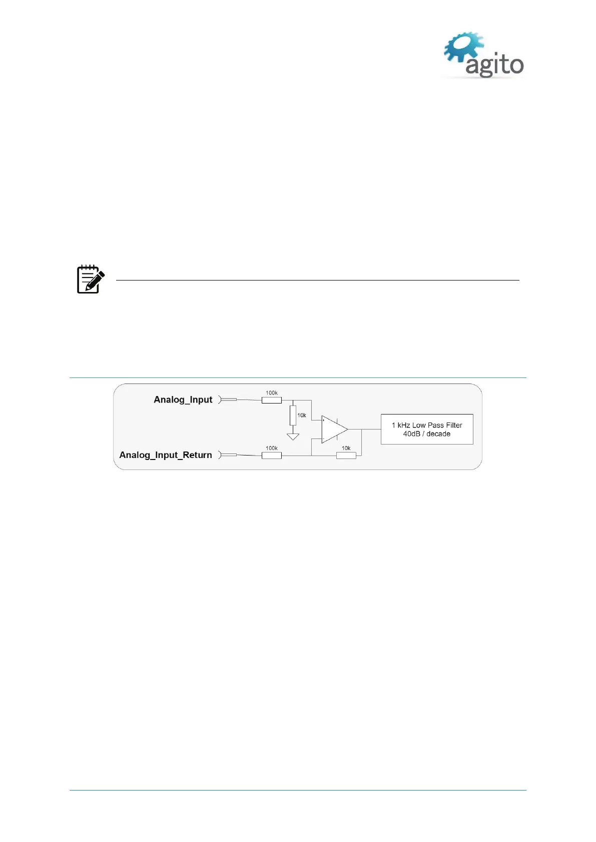
Figure 25. Analog inputs
The electrical interfaces of analog inputs 1, 2, 3, and 4 are identical.
The analog input range is -12V to +12V, and resolution is 16 bits.
The analog input is designed for standard differential analog input, with a simple input circuit,
having an input resistance of ~60 kW.
For single-ended analog inputs, be sure to connect the return line to GND. Do not leave it
unconnected.
Input circuit bandwidth: 1 kHz, -40 dB/decade
The controller software provides the following parameters to control the analog input reading:
Filter
Offset
Deadband
Gain


 To Next Page