Electrical Interfaces
AGD301 Product Manual Rev.2.0 Page 49
The same electrical signal is sent as a differential pair, each in its own conductor. The pair is wired
as a twisted pair.
The differential outputs in the AGA10x amplifiers are implemented according to the RS422
standard.
The differential outputs are inactive during power on, until they are controlled by the drive
firmware and the user parameters.
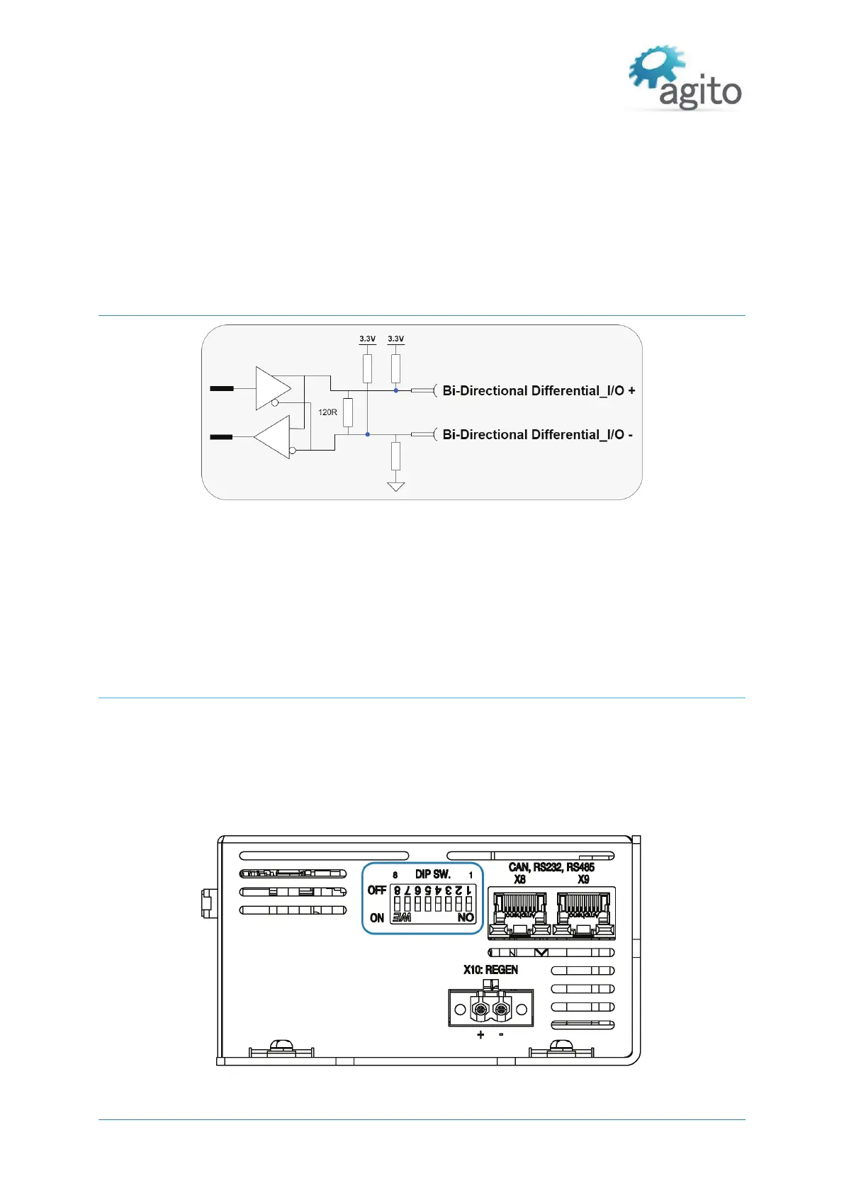
Bi-directional Differential I/Os
Figure 29. Bi-directional differential I/Os
The bi-directional differential output is configurable by software to be a differential output or
differential input.
Both + and - pins are pulled up to 3.3V.
There is a 120Ω termination resistor between the + and - pins.
3.4.15 DIP Switches
The AGD301 includes 8 DIP switches to define CAN or Ethernet address offset, to connect a 120Ω
CAN terminator resistor, to activate firmware download mode, and set other functions. These are
hardware configurations that are typically done only once, during product installation.
The value of the DIP switches, as read by the controller during power on (or reset), can be queried
using ADebugData[4] in Agito PCSuite terminal.
Figure 30 DIP Switches


 To Next Page