Electrical Interfaces
AGD301 Product Manual Rev.2.0 Page 48
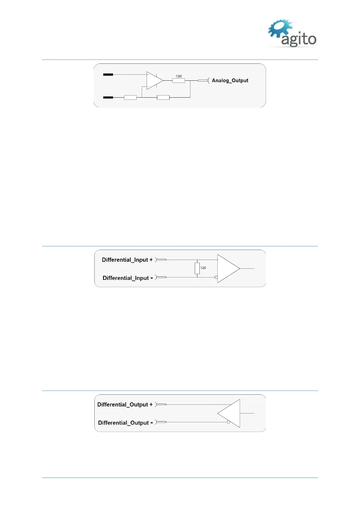
Analog Output
Figure 26. Electrical Interfaces – Analog Output 1 to 2
The electrical interfaces of all analog outputs are identical.
The analog output range is from -12V to +12V, with resolution of 16 bits.
Output resistance is 10W.
Output current is up to ±2mA, without internal current limitation.
Analog outputs are controlled by the controller software in few operational modes:
Analog output controlled by the user program for a general purpose.
Analog output reflects the internal value of a user selected parameter (position, position
error, velocity, current, or any parameter/status of the controller), with a user defined scaling
factor, for easy monitoring using an external oscilloscope.
Differential Inputs
Figure 27. Differential inputs
Differential inputs use two complementary signals (Differential_Input+ and Differential_Input-) to
receive information.
The same electrical signal is sent as a differential pair, each in its own conductor. The pair is wired
as a twisted pair.
The differential inputs in the AGD301 are implemented according to the RS422 standard.
Each differential input has a 120 Ω terminator.
Differential Outputs
Figure 28. Differential outputs
Differential outputs use two complementary signals (Differential_Output+ and
Differential_Output-) to receive information.


 To Next Page