Motor Configuration
AGD301 Product Manual Rev.2.0 Page 53
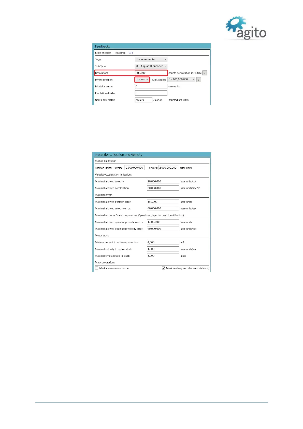
Figure 35. Feedback Parameters
The value of Invert direction affects commutation of the motor. The encoder must be moving in
the positive direction during auto-phasing process.
5. Click Next to setup position, velocity and motor stuck protection. Fill in the limits according to the
application requirements.
Figure 36. Position and Velocity Protection
6. Click Next to configure current and voltage limits. It is important to refer to motor’s
specifications. The limits entered here must be within the motor operating limits to avoid
damaging the motor.


 To Next Page