14
SW2
1 2 3
4
5 6 7
8
DC24V
Power
B2
B1
IN
A2
A1
OUT
R2
R1
ON
OFF
SW3
LAN
1 2 3
4
DC24V
R1
R2
MODE
EXPAND
STANDARD
1P
NP
1P
NP
1P
NP
1P
NP
1P
NP
1P
NP
1P
NP
1P
NP
1P
NP
1P
NP
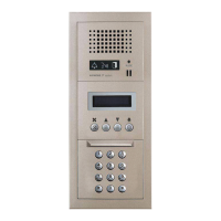
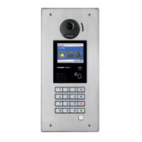
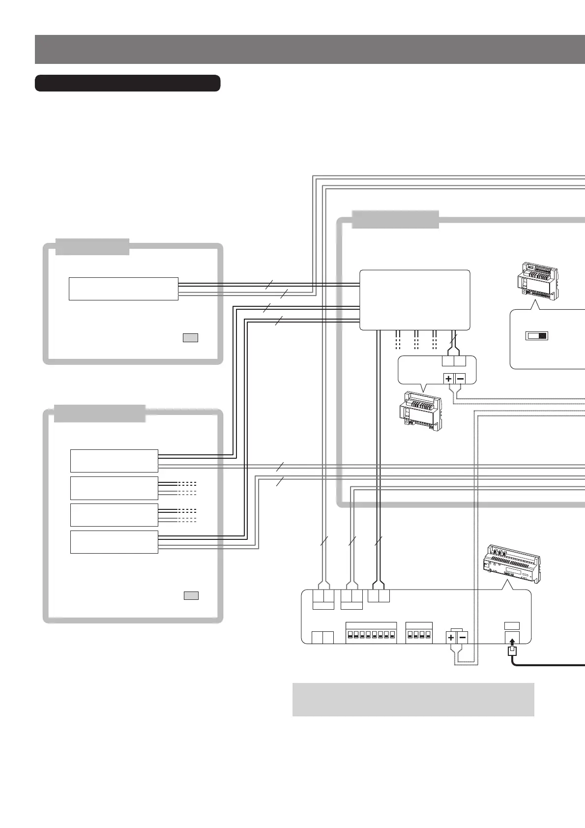
Entrance station 1
Entrance station 2
Entrance station 3
Entrance station 4
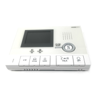
Guard station
Guard station
Entrance stations
Video bus control unit
GT-VBC
Bus control unit
GT-BC
Multi-building
control unit
GT-MCX
WIRING
Main section (standard system)
DP (Distribution Point)
(Not provided by
Aiphone except for
Europe and North
America.)
Common area
*2
*2: NOTE: Do not route a CAT5e/6 cable outdoors from a multi-building
control unit directly. When routing a CAT5e/6 cable outdoors
from a switching hub, use a model that supports outdoor wiring.
*1
Refer to the installation manual GT SYSTEM/
Standard & Expanded System section
4-2
for detailed connection diagrams.
Refer to the installation manual GT SYSTEM/
Standard & Expanded System section
4-3
for detailed connection diagrams.

 Loading...