5
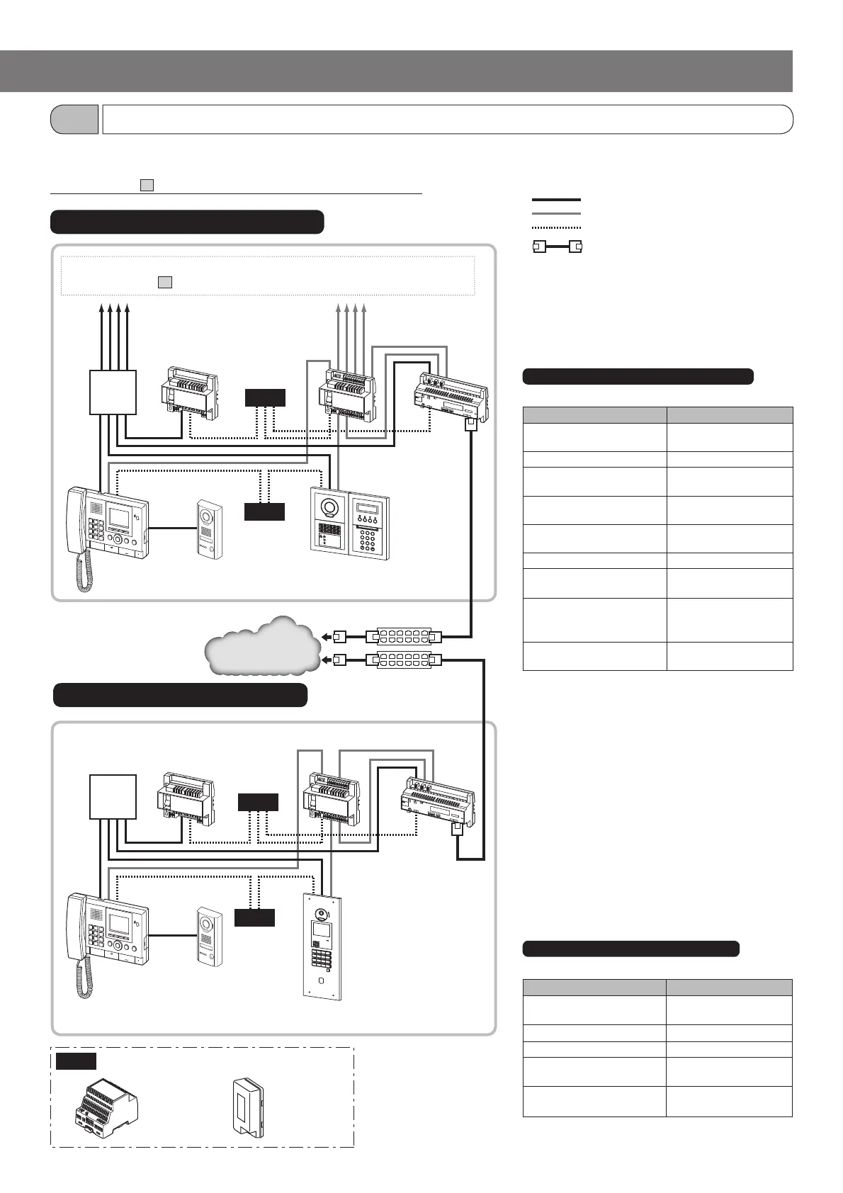
The following is a multi building system confi guration example that consists of standard systems as tenant and main sections. Refer to the
installation manual GT SYSTEM/Standard & Expanded System for details about the standard system confi guration.
*Refer to section
4
"WIRING" for details about wiring and connection.
PS24
PS-2420
PS-2420S
PS-2420UL
PS-2420BF
PS-2420DM
PS24
PS24
PS24
PS24
2
B
A
C
3
E
D
F
5
K
J
L
8
U
T
V
4
H
G
I
6
N
M
O
1
0
9
Y
X
W
Z
7
R
Q
P
S
*2
Residential/tenant trunks 1 to 4 [max. 48 stations (max. 25 per trunk)]*
1
* Refer to section
4
"WIRING" for details about the residential/tenant stations.
Power supply
DP
DP
: Audio signal line
: Video signal line
: Power supply line
: CAT5e/6 cable (100BASE-TX)
Video bus
control unit
GT-VBC
GT-VBC
Bus control unit
GT-BC
GT-BC
Multi-building
control unit
GT-MCX
GT-MCX
DP: Distribution Point
(Not provided by Aiphone except for Europe
and North America.)
GT-MKB-N
Guard station
GT-MKB-N
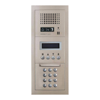
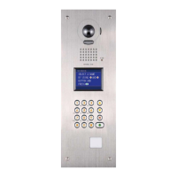
Entrance station (Modular type
and all-in-one type enabled)
Entrance station
GT-DMB-N/GT-DMB-LVN
Tenant section (standard system)
Capacity: Max. 24 sections
Device Capacity (per section)
Entrance station Max. 4 (max. 3 per trunk
from the DP) *
3
*
4
Guard station (GT-MKB-N) Max. 1
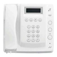
Residential/tenant station Max. 48 (max. 25 per
trunk from the DP) *
5
Residential/tenant stations in
the same residence/tenant
Max. 4 *
6
4-way video junction unit
(GT-4Z)
Max. 6 per trunk
Bus control unit (GT-BC) 1 required
Video bus control unit
(GT-VBC [STD])
Max. 1
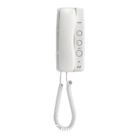
Sub residential/tenant station
(GT-2H-L, GT-2H)
Max. 3 (connectable to the
residential/tenant station
GT-2C only)
Multi-building control unit
(GT-MCX)
1 required
*3: If GT-DB-V, GT-DB-VN or an external door release
button is connected to an entrance station that
includes GT-SW, a maximum of 3 entrance stations
can be connected to the system.
*4: Up to 3 entrance stations can be connected per
audio signal line from the DP. If GT-DB-V or
GT-DB-VN is used in an entrance station, the
maximum number of entrance stations is 2.
*5: The maximum is 100 stations with GT-1D only.
(GT-1D: Max. 50 stations per trunk)
*6: Max. 4 under the following conditions only:
• GT-1A or GT-1D × Max. 4
• GT-1C7(-L) × 1 + GT-1A or GT-1D × Max. 3
• GT-1M3(-L) × 1 + GT-1A or GT-1D × Max. 3
• GT-1M3(-L) × 2 + GT-1A or GT-1D × Max. 2
• GT-2C(-L) × Max. 4
Main section (standard system)
Capacity: Max. 8 sections
Device Capacity (per section)
Entrance station (GT-DMB-N
or GT-DMB-LVN) *
7
Max. 4 (max. 3 per trunk
from the DP) *
3
*
4
Guard station (GT-MKB-N) Max. 1
Bus control unit (GT-BC) 1 required
Video bus control unit
(GT-VBC [STD])
Max. 1
Multi-building control unit
(GT-MCX)
1 required
*7: Only all-in-one type entrance stations can be used in
a main section.
Modular type entrance stations cannot be used.
LAN
SYSTEM CONFIGURATIONS
Multi building consisting of standard systems
1-2
Main section (standard system)
Tenant section (standard system)
Switching hub
Switching hub
*1: Refer to Standard & Expanded System Manual
about residential/tenant station confi gurations.
*2: Make sure that a power supply is shared
between GT-BC and GT-VBC.
Video door station
JO-DV
Video door station
JO-DV
 Loading...