20
ON
OFF
23
1
SW2
1 2 3
4
5 6 7
8
SW3
1 2 3
4
ON
OFF
ON
OFF
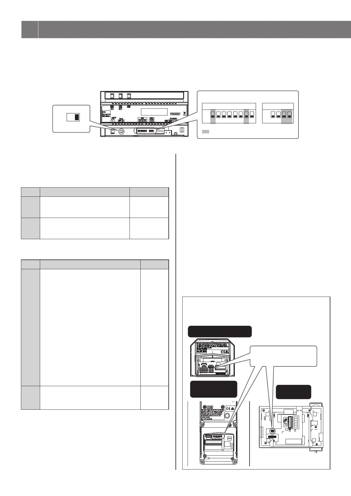
The multi building control unit, GT-MCX, needs to be initially set up via the DIP switches before powering on. The IP address will be assigned
based on the section ID setting. (192.168.1.50 + Section ID)
Confi guration will then need to be completed using the GT Setup Tool on a PC.
* Refer to the GT SYSTEM Multi Building System Setting manual for details about confi guring the system settings.
* It is recommended to discuss the installation and setting method with the person responsible for installation in advance.
1 Power switch
Set the switch to ON when using this unit.
2 SW2
No. Function Default
2 to 6
Sets the local section ID.
See "Section ID setting" below for
details.
OFF/OFF/OFF
OFF/OFF/OFF
(ID 1)
8
Resets the passcode for the installer or
administrator when this unit is
initialized by setting this switch to ON.
OFF
3 SW3
No. Function Default
1
Sets whether DHCP is active or not.
ON: DHCP is inactive.
An IP address decided by the PC Link
Setting method will be assigned to the
unit.
(Default IP address - 192.168.1.50)
The IP address is set as follows.
192.168.1.
α (α = 50 + Section ID)
[Example]
Section ID = 11
IP Address = 192.168.1.61
* For detailed explanation of IP setting,
please refer to GT SYSTEM Multi
building system Setting manual.
OFF: DHCP is active.
An IP address will be assigned
automatically.
OFF
2
Initialization of the settings.
* The set date is not initialized.
Follow the procedure below.
OFF
How to initialize GT-MCX (3 SW3 - "2")
Procedure:
1 Turn the power switch OFF for the unit to be
initialized.
2 Set the DIP switch "2" in SW3 to ON position.
3 Turn the power switch ON.
The status LED of the unit will fl ash for approximately 30
seconds; wait until the LED stops fl ashing.
* In the case date & time has not been set, the LED will
continue to fl ash in approximately 6 second intervals after 30
seconds have passed.
4 The unit has now been initialized. Set the DIP switch
"2" in SW3 to OFF position.
5 Turn the power switch ON.
This step completes the initialization procedure.
NOTE :
ID1 is unavailable for the entrance station and the guard station.
(ID1 of each station is used for GT-MCX in a multi building
system.)
5 SWITCH SETTINGS
Power switch
DIP switch
: Do not change these switches.
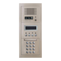
Entrance station
(GT-DMB-LVN,
GT-DMB-N)
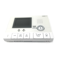
Guard station
(GT-MKB-N)
ID1 is unavailable.
Audio module
(GT-DB, GT-DB-V, GT-DB-VN)

 Loading...