23
What is “ground fault”?
"Ground fault" means the state where internal copper wire is touching a metal part (ground) in the building because the coating on the wiring
of the intercom system is peeled off. This may cause the equipment to malfunction. Being in the ground fault state, the whole system will be
damaged seriously by a "power surge."
Inspection conditions:
Important
• Check that the power supply is grounded properly as described in
6-1
.
• Before starting inspection, make sure all control units (GT-BC, GT-VBC, GT-BCXB, GT-VBX, GT-MCX), entrance station, and guard station
are turned on. (Only when the equipment is installed)
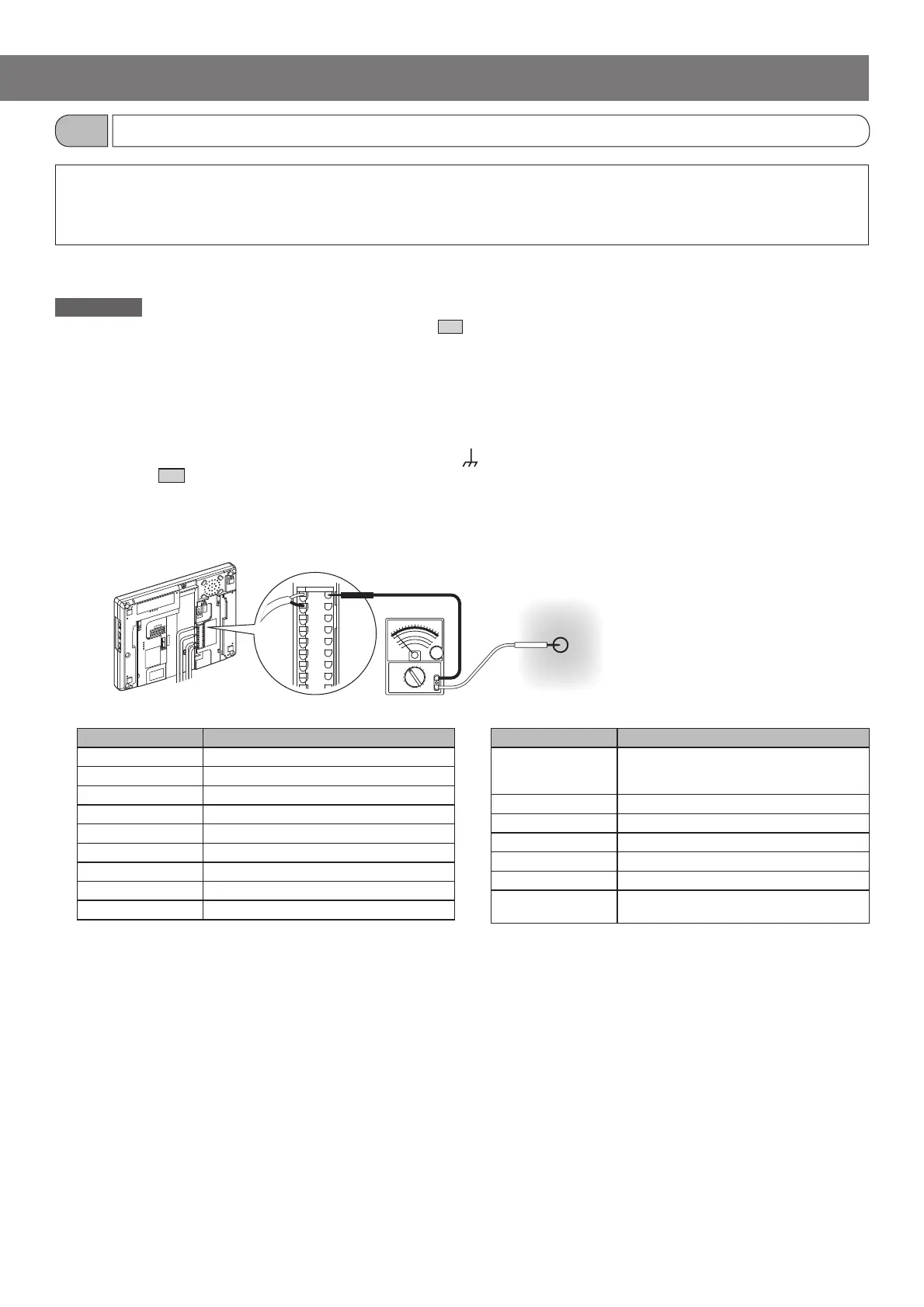
Inspection procedure:
1 Set the tester for around 50V DC.
2 Put one tester rod to the power supply ground terminal [ ]. If the power supply is not nearby, fi nd a grounding point
referring to
6-1
.
3 With one tester rod put on the power supply ground terminal, put the other to the following terminals to be
inspected.
4 If the tester needle does not swing in step 3, it will be judged "no ground fault.".
* If the tester needle swings, there is a ground fault in wiring between the power supply and the inspected point.
(The same is true in the case where the needle swings reversely.)
Solution:
Divide the wiring into sections or trunk lines, identify the ground fault point, and remove the cause.
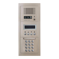
Product name Terminal to be inspected
GT-BC All [R1] and [R2]
GT-BCXB-N All [R1] and [R2]
GT-VBC All [A1], [A2], [B1] and [B2]
GT-VBX All [A1], [A2], [B1] and [B2]
GT-MCX [R1], [R2], [A1], [A2], [B1], [B2]
GT-VB [A1], [A2]
GT-DB(-V, -VN) [R1], [R2]
GT-DMB(-V, -LVN) [R1], [R2], [A1], [A2]
GT-MKB-N [R1], [R2], [A1], [A2], [B1], [B2]
Product name Terminal to be inspected
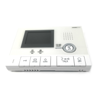
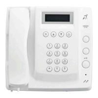
GT-2C(-L)
GT-1C7(-L)
GT-1M3(-L)
All [R1], [R2], [B1] and [B2]
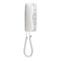
GT-1A, GT-1D All [R1] and [R2]
GT-4Z All [R1], [R2], [B1] and [B2]
GT-1Z All [B1] and [B2]
GTW-LC [R1], [R2]
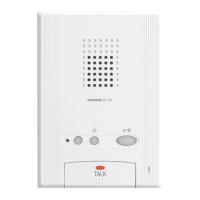
JO-DV [A1], [A2]
DP (Distribution
Point)
(Each line)
Power supply ground terminal or
grounding point
(e.g. GT-1C7)
Checking "ground fault" with tester
6-2
CHECK FOR INSTALLATION

 Loading...