16
A2
A1
A2
A1
A2
A1
A2
A1
A2
A1
A2
A1
A2
A1
A2
A1
COMMON1
SUB1
B2
B1
B2
B1
DC24V
R1
R2
MODE
EXPAND
STANDARD
OUT
IN
OUT OUT
2
OUT
1
B2
B1
B2
B1
B2
B1
B2
B1
3
OUT
B2
B1
4 6
5
IN IN
1 2
A2
A1
A2
A1
A2
A1
DC24V
PS24
AC
PS24
AC
SW2
1 2 3
4
5 6 7
8
DC24V
Power
B2
B1
IN
A2
A1
OUT
R2
R1
ON
OFF
SW3
1 2 3
4
1P
NP
1P
NP
1P
NP
1P
NP
1P
NP
1P
NP
1P
NP
1P
NP
1P
NP
1P
NP
1P
NP
1P
NP
1P
NP
1P
NP
1P
NP
1P
NP
Entrance station 5
Entrance station 6
Entrance station 7
Entrance station 4
Entrance station 3
Entrance station 2
Entrance station 1
Guard station
Common trunk line 1
Guard station
Expanded video bus control unit
GT-VBX
Video bus control
unit GT-VBC
Bus control
unit GT-BC
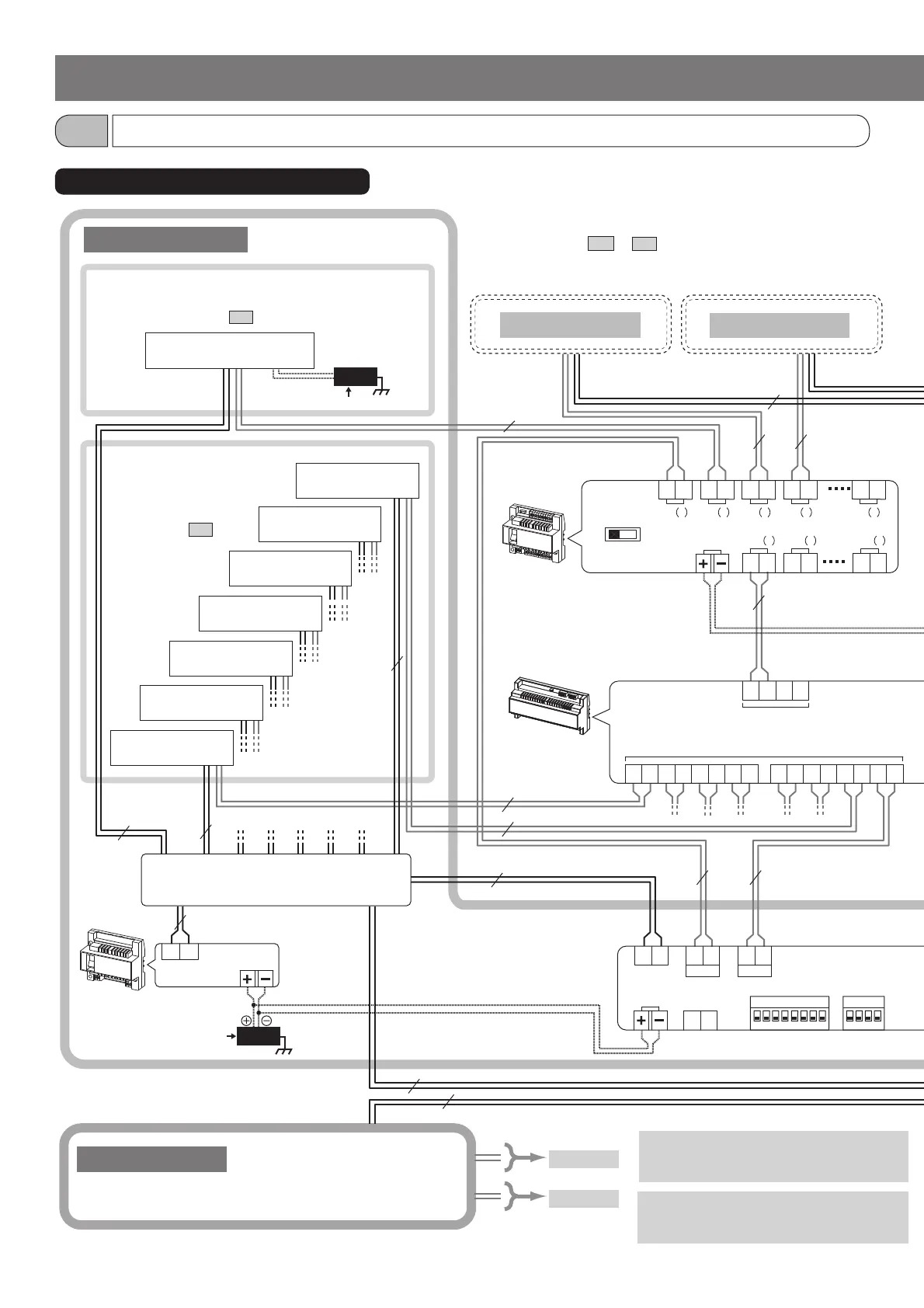
The following is a connection diagram example of a multi building
system consisting of expanded systems as tenant and main sections.
* The wiring methods differ depending on the equipment used. Refer
to the installation manual GT SYSTEM/Standard & Expanded
System sections
4-2
to
4-4
for the detailed wiring diagrams of
entrance stations, guard stations, and residential/tenant stations.
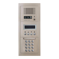
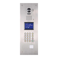
Entrance stations
Sub trunk line 1-B
* Make connections in the same method as common trunk line 1.
However, do not connect the GT-MCX to common trunk line 2.
Common trunk line 2
Sub trunk line 1-A
Multi building consisting of expanded systems
4-2
Tenant section (expanded system)
WIRING
To GT-VBX
To GT-VBC
NOTE
The GT-MCX must be connected to the
common trunk line 1.
*1:
*1
*1
DP (Distribution Point)
*3: Switching hub requirement (third party product)
• Packet delivery: Multicast
• Transmission rate: 100 Mbps or more
Refer to the installation manual GT SYSTEM/Standard &
Expanded System section
4-2
for detailed connection diagrams.
Refer to the installation
manual GT SYSTEM/
Standard & Expanded
System section
4-3
for
detailed connection
diagrams.
 Loading...