Page
13Air Techniques, Inc. Air Techniques, Inc.
Page
12
ELECTRICAL CONNECTIONS
Remove all power to the system prior to working
within the electrical box. Contacting high voltage
can cause serious injury or even death.
All systems must be wired directly from
an electrical box that complies with
local electrical codes.
Figure 8. Remote Switch Connection to Main Board
Remote Switch Connections.
As shown by Figure 8, connections are made via connectors J4 and J6 of the main board.
VDC Connections.
Make the 6 VDC connections shown by Figure 9, View A, for Remote Panel Switch #53202-1 pro-
vided by Air Techniques. Make the 24 VDC connections shown by Figure 9, View B, for Remote Panel
Switch #53201-1. When using a switch not provided by Air Techniques, all remote system status
indication is lost.
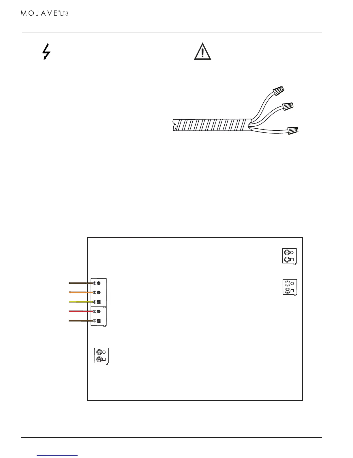
Figure 7. MOJAVE LT3 Power Connection
MOJAVE LT3 Pump Direct Power Connection.
Each unit is wired directly to an dedicated 220V, 20 AMP single
phase 50/60 Hz circuit via a disconnect box with approved ground.
BLACK
WHITE
Disconnect boxes should be mounted no
more than 3 feet of the installation center
line.
Figure 7 shows the wiring of the electrical BX
cable used to connect the LT3 directly to facility
input power.
Supplied 6-Foot BX Cable
from Electrical Box of Pump
GREEN YELLOW
STRIPE
(L2)
(L1)
(GND)
AUX
J9
J14
J10
ETH
AUX_ALARM
J6
J4
ORN
YEL
RED
BRN1
BRN2
To
Remote
Switch
Connect by
Wire Color