Page
9Air Techniques, Inc. Air Techniques, Inc.
Page
8
INSTALLATION INFORMATION
Installation Notes.
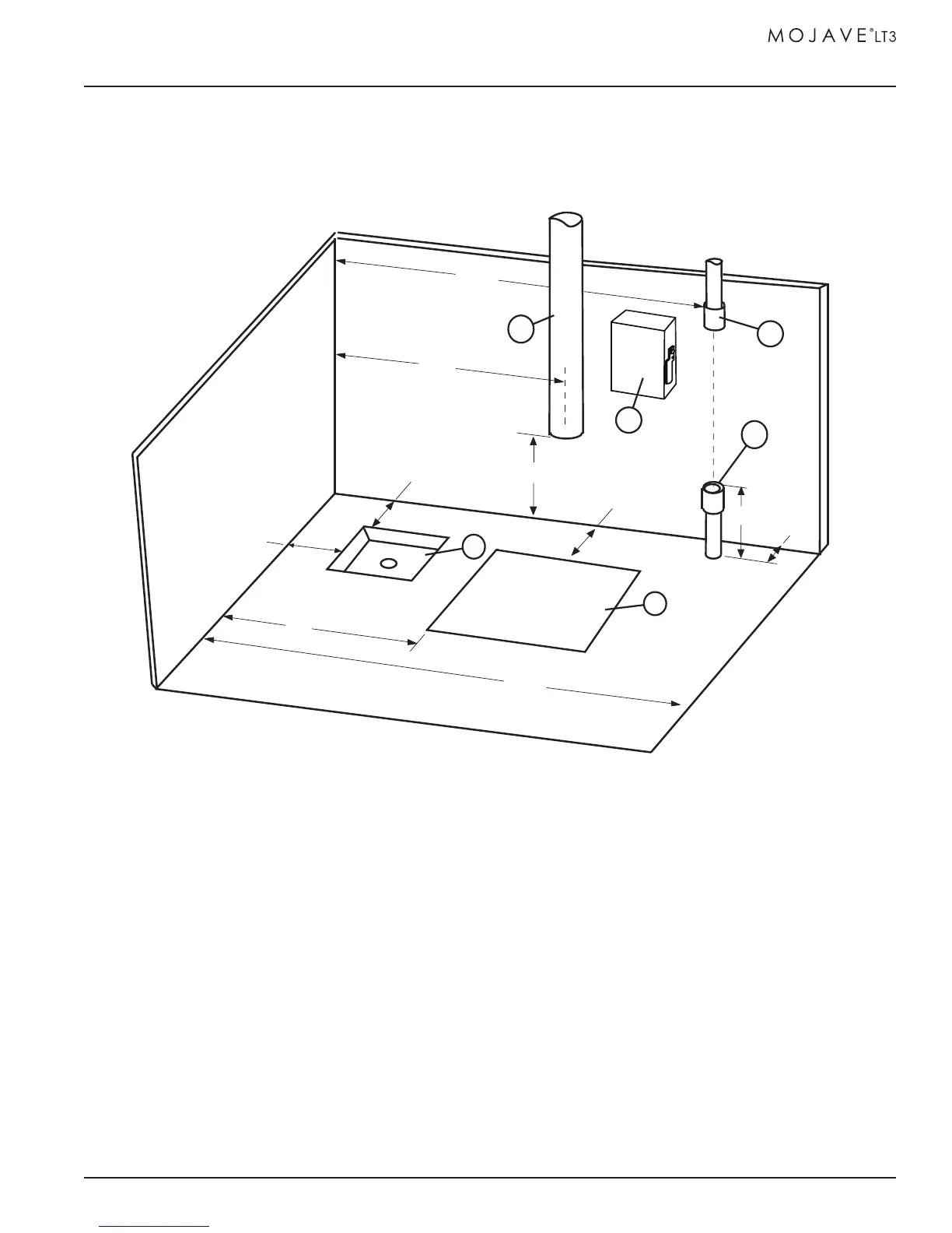
Installation Layout Space. Figure 4 shows the requirements for the installation of MOJAVE
LT3. Please note that all units are shipped with leveling feet set to lowest position. Heights can be
increased by 1 inch by adjusting the leveling feet. Refer to Figures 5 and 6 for connection details.
A. PUMP INSTALLATION SPACE - Area for MOJAVE LT3 pump in typical installation.
B. SEWER DRAIN - Provide a drain for the removal of waste liquids from the Air/Water Separator assembly.
Use an open drain pipe (1 ½ inch P-Trap with 1 inch air gap or floor sink) or a closed vented drain.
See Figure 6.
C. HEAT EXHAUST - Refer to Figure above and see Plumbing Requirements for the exhaust vent line required
for MOJAVE LT3. Schedule 40 pipe can be used on MOJAVE LT3.
D. PUMP ELECTRIC SERVICE - The MOJAVE LT3 pump is wired directly with a dedicated 220V, 20 AMP, single
phase 50/60 Hz circuit. If Main Circuit panel is not located in equipment room, a disconnect box with approved
ground is needed for each pump. Disconnect boxes should be mounted no more than 3 feet of the installation
center line.
E. OVERHEAD INSTALLATION VACUUM LINE - See Plumbing Requirements for MOJAVE LT3 connection.
F. SUB FLOOR INSTALLATION VACUUM LINE - See Plumbing Requirements for MOJAVE LT3 connection.
48"
4"
4"
20"
Sewer Drain
4"
MOJAVE LT3
INSTALL
AREA
60"
1"
12"
24"
36"
E
A
B
C
D
F
Figure 4. MOJAVE LT3 System Floor Plan