5-2 EB AT-RP-4GU EN
Mounting and assembly
Before mounting the actuator over the valve, make sure the
following conditions are met:
− The actuator is not damaged.
− The type designation, material and temperature range of
the actuator match the ambient conditions (temperatures
etc.). Refer to ‘Markings on the device‘ in section 2 for
nameplate details.
− Check compatibility of the valve stem to the actuator bore.
The length, size and configurations must match.
− Check compatibility of actuator, valve and bracket bolting
pattern.
− Before fitting the actuator over the valve, make sure that
the actuator and the valve are correctly oriented, with re-
ference to the rotation direction and fail action required.
− Make sure that the tubing, fittings and seals connected to
the actuator are cleaned to prevent foreign matter/objects
entering into the actuator’s chambers.
− When fitting accessories over the actuators, assemble
them in such a way that the emergency controls are easily
accessible for emergency manual operation.
− Check that the exhaust ports are not obstructed.
− Remove the plugs from the actuator air connections during
installation and operation, protect and close the air
connections which may not being used immediately.
− Make sure that the operating pressure media composition
used for the actuator operation meets the operating condi-
tions given in this manual and corresponds to what the ac-
tuator was manufactured for. Refer to section 3 ‘Design
and principles‘.
− It is the user responsibility to ensure that actuator and con-
trol components must be protected from electrical spikes,
surge and lightning strikes as well as all magnetic fields.
− Prevent any dangerous and/or corrosive substances in the
working environment enter into the internal chambers by
using adequate filters and/or solenoid valves and/or any
other appropriate system.
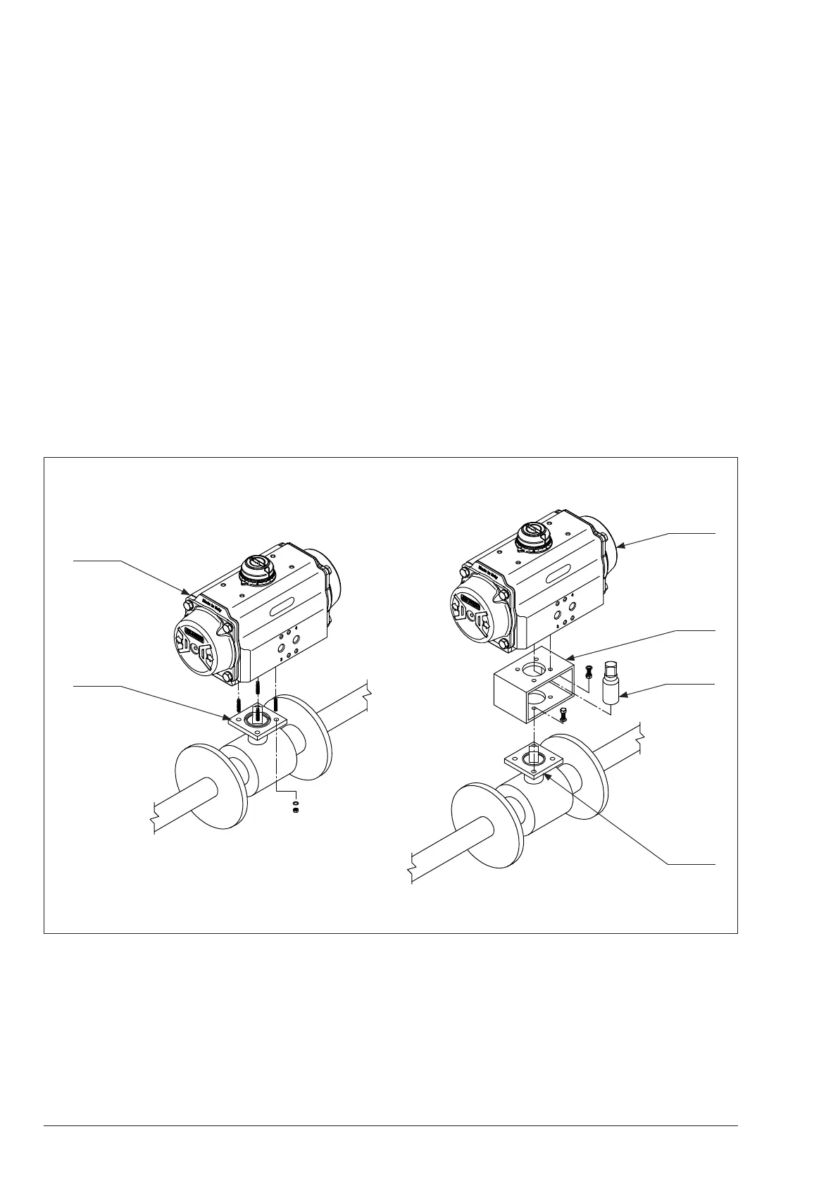
Fig. 5-2
Coupling
Bracket
Valve
interface
Actuator
Valve
interface
Actuator
DIRECT MOUNTING MOUNTING WITH BRACKET
Refer to Fig. 5-2 and proceed as follows to mount the actua-
tor over the valve:
1.
Disconnect any electrical/pneumatic/hydraulic power
supply.
2. Lay out the necessary material and tools to have them rea-
dy during mounting.
3. The actuator is supplied in the fail position (for single-ac-
ting), so drive the valve in the right position as per the ac-
tuator fail position.
4.
Clean the actuator‘s bore and the bottom flange.
5.
Clean the valve and the actuator interface to remove com-
pletely any lubricant.