EB AT-RP-4GU EN 5-1
Mounting and assembly
5 Mounting and assembly
The work described in this section is only to be performed by
fully trained and qualified personnel.
5.1 Preparation for installation
If the actuator was shipped already assembled over the valve,
the setting of the actuator and control system (if any) should
have been already done by the valve manufacturer or auto-
mation center.
If the actuator was shipped separately from the valve, the set-
ting of the actuator and control system must be done while as-
sembling the actuator on top of the valve.
The actuator assembly on valve can be performed by:
− Mounting directly the actuator over the valve interface
− Assembling a bracket and a coupling between the actua-
tor and the valve.
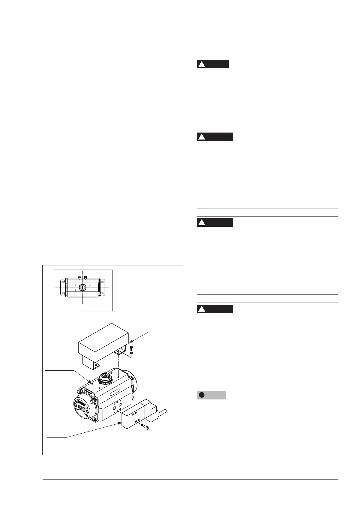
5.2 Control and signal devices assembly
The AIR TORQUE 4
th
GU Series actuators can be controlled by
directly mounted devices or remote control systems. Therefore
AIR TORQUE actuators have direct mounting interfaces (Fig.
5-1) in order to allow control and signal devices assembly
(e.g. solenoid valve, positioner, switchbox, etc) and threaded
connections for remote control systems.
Î Refer to the documentation available from control and sig-
nal devices manufacturers for mounting and operating in-
structions.
Fig. 5-1
Position
indicator
Solenoid
valve
Ancillary
attachments
Switchbox
and bracket
Top view
5.3 Mounting the actuator over the valve
Risk of bursting in the actuator
Pneumatic actuators are pressure equipment that may burst
when handled incorrectly. Flying projectile fragments or com-
ponents can cause serious injury or even death.
Î Before starting any work on the actuator disconnect all
pneumatic / hydraulic / electrical supplies and discharge
the pressure from the actuator.
Crush hazard arising from moving parts.
The actuator and the valve assembly contains moving parts,
which can injure hands or ngers.
Î Do not touch or insert hands or nger into moving parts.
Î Before starting any work on the actuator disconnect all
pneumatic / hydraulic / electrical supplies and discharge
the pressure from the actuator.
Î Do not impede the movement of the pinion and the pistons
by inserting objects into the actuator.
Risk of damage and malfunction due to torque limit viola-
tion.
Considering the maximum actuator output torque, the maxi-
mum air supply pressure and the maximum valve torque, ac-
cording to ISO 5211, the actuator maximum transmissible
output torque must not exceed the torque limit in relation to
the available ISO ange and the drive shaft connection.
Î Refer to section 2 ‘Markings on the device‘ for nameplate
details.
Risk of personal injury due to preloaded and compressed
springs.
End caps are under tension due to compressed springs.
Furthermore incorrect spring cartidges disassembly could re-
sult in serious injury.
Î Before starting any work on the actuator disconnect all
pneumatic / hydraulic / electrical supplies and discharge
the pressure from the actuator.
Î Make sure that the actuator is in the closed position (0°).
Risk of actuator damage due to excessively high or low tigh-
tening torques.
Observe the specied torques on tightening actuator compo-
nents (bolts and nuts). Excessive tightening torques lead to
parts wearing out quicker. Parts that are not tightened enough
may loosen.
Î Refer to section 15.2 ‘Tightening torques‘.
DANGER
!
WARNING
!
WARNING