9-6 EB AT-RP-4GU EN
Service
Double acting actuators
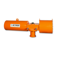
− Unscrew completely the end cap bolts (13) as per the se-
quence shown in the Fig. 9-5.
− Remove the end caps (30).
− Remove the o-rings (14). (Fig. 9-6)
9.3.4 Pistons disassembly
Refer to Fig. 9-1 and Fig. 9-7.
Fig. 9-7
60/60.1
16 40
40
16
15
15
50
40 05
− Holding the body (50) with a bench vice or a similar de-
vice, rotate the drive shaft (60/60.1) until the pistons (40)
are disengaged.
− Remove o-rings (16), the piston backs (05) and the piston
head bearings (15).
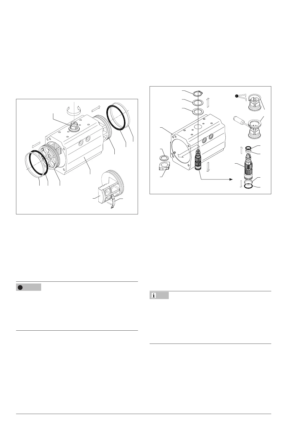
9.3.5 Drive shaft disassembly
Refer to Fig. 9-1 and Fig 9-8.
Risk of spring clip damage due to incorrect disassembly.
During disassembly the spring clip (18) can get overstressed if
not carefully handled.
Î Use proper tools to disassemble the spring clip.
Î In case of spiral spring clip (18) refer to the disassembly
and reassembly instructions available from AIR TORQUE.
− Remove the spring clip (18) by means of snap-ring pliers
or a screwdriver for spiral rings.
− Remove the thrust washer (10) and the external thrust bea-
ring (08).
− Apply downward force to the top of the drive shaft
(60/60.1), until it is partially out of the bottom of the body
and remove the internal thrust bearing (08) and the oc-
ti-cam (01).
− Push the drive shaft (60) completely out of the body.
If needed, gently tap the top of the drive shaft (60) with a
plastic hammer.
− Remove the drive shaft top bearing (06) and bottom bea-
ring (07).
− Remove the drive shaft top o-ring (21) and bottom o-ring
(20).
Fig. 9-8
06
07
21
20
60
60.1
50
18
08
01
10
08
18
9.4 Service operations
Inspect and clean every single component.
Inspect, clean and replace bolts and nuts, if needed.
Discard and replace the damaged soft components available
in the spare parts kit.
Î Refer to the spare parts kit data sheet [RP10600E] and to
the Rubber products storage instructions [T 3.3.3.1 EN].
Clean and lubricate every o-ring housing.
Î Refer to the section 15.3 ‘Lubricants‘.
9.5 Reassembly
in case of special actuators functions / features (R&P) refer to
the corresponding instructions:
- Fail mid “FM“ → EB AT-RP-4GU-FM,
- 180° SR → EB AT-RP-4GU-180SR,
- HCD → EB AT-RP-4GU-HCD,
- 3P / 3PD → EB AT-RP-4GU-3P.
Proceed as follows for the standard assembly of 4
th
GU series
actuators (AS-ST code indicated in the nameplate).
Î Refer to the TYAS technical data sheet in case of actuators
with different function/rotation.
Î Refer to the Catalogue 4THGU-E for actuators different as-
sembly codes.
NOTICE
!
Note