EB AT-RP-4GU EN 9-5
Service
Risk of components damage due to incorrect disassembly.
During disassembly the end caps can be damaged due to un-
even force generated by compressed springs.
Î Remove the end caps as shown in Fig. 9-4 keeping a
constant distance (A = B) between the actuator body and
the end cap interface.
Î Observe the specied sequence shown in Fig. 9-5.
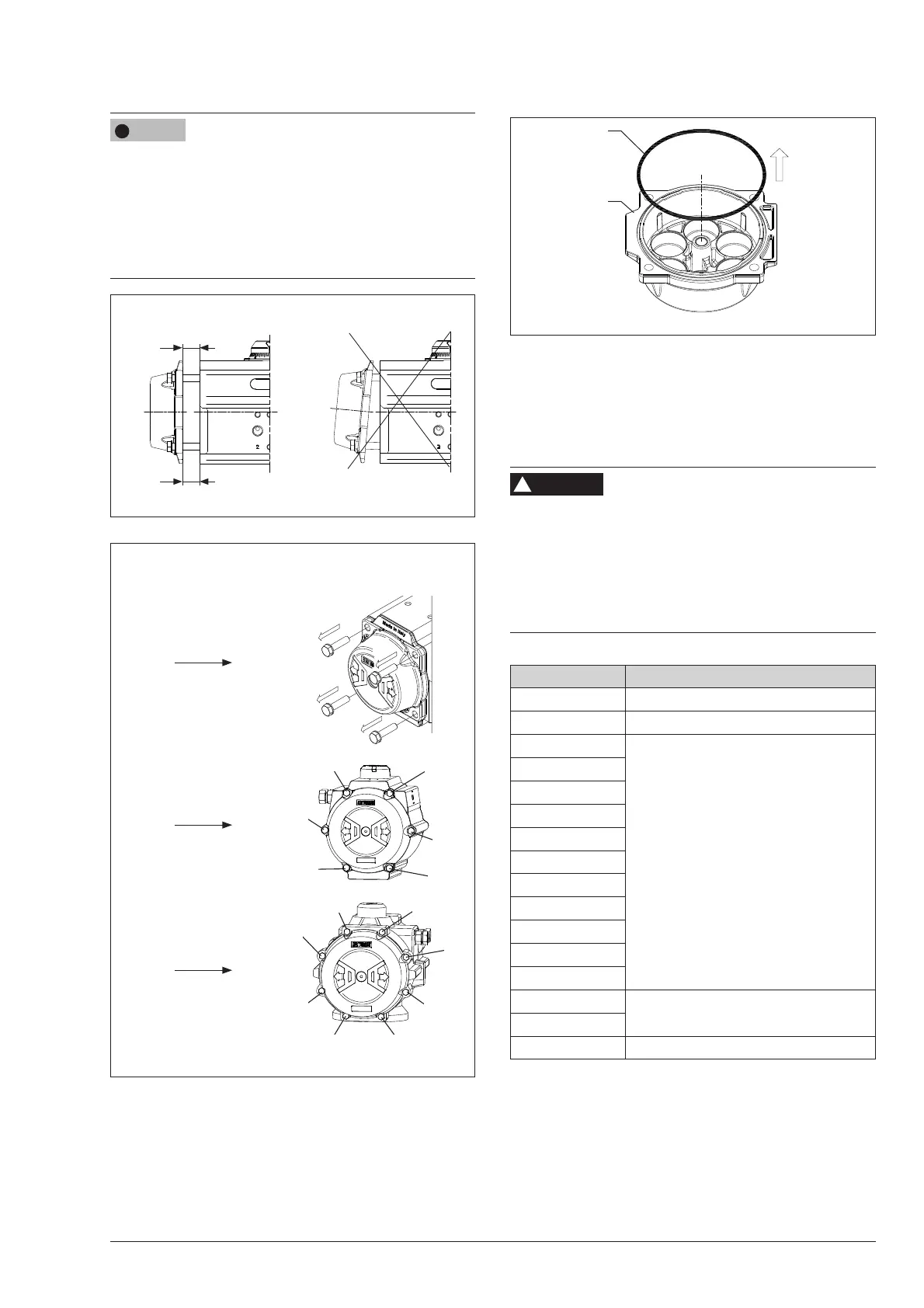
Fig. 9-4
B
A
A = B
Fig. 9-5
3
2
4
1
1
2
5
3
4
6
1
7
2
5
3 8
4
6
TOTAL QUANTITY OF
CAP SCREWS (13)
PER ACTUATOR:
− 8
− 12
− 16
SEQUENCE OF
DISASSEMBLY:
Fig. 9-6
14
30
30R
Spring return actuators
− Release the springs compression by partially unscrewing
each end cap bolt (13) 1 turn at a time as per the sequen-
ce shown in Fig. 9-5 for the number of turns indicated in
Table 9-2.
Risk of personal injury due to compressed springs.
End caps are under tension when the springs are compressed.
Î If there is still force on the end cap (30/30R) after
uscrewing the cap screws (13) for the number of turns in-
dicated in Table 9-3, the spring cartridge may have been
damaged or the pistons are not completely closed: stop
the disassembly and contact AIR TORQUE.
Table 9-3
ACTUATOR MODEL NUMBER OF TURNS FOR SCREWS (13)
AT045U 16 ÷18 turns
AT051U 26 ÷ 28 turns
AT101U
5 ÷ 7 turns
AT201U
AT251U
AT301U
AT351U
AT401U
AT451U
AT501U
AT551U
AT601U
AT651U
AT701U
6 ÷ 8 turns
AT751U
AT801U 8 ÷ 10 turns
− Completely unscrew and remove the end cap bolts (13)
− Remove the end caps (30).
− Remove the spring cartridges (17).
− Remove the o-rings (14). (Fig. 9-6)
NOTICE
!
WARNING
!