9-4 EB AT-RP-4GU EN
Service
9.3 Disassembly
Î Refer to the Fig. 9-1 and Table 9-2 for parts list.
Note
In case of special actuators functions / features (R&P) refer to
the corresponding instructions:
- Fail mid “FM“ → EB AT-RP-4GU-FM,
- 180° SR → EB AT-RP-4GU-180SR,
- HCD → EB AT-RP-4GU-HCD,
- 3P / 3PD → EB AT-RP-4GU-3P.
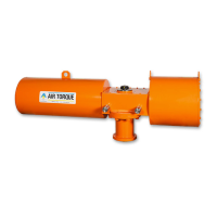
9.3.1 Position indicator and graduated
ring removal
Refer to Fig. 9-1 and Fig 9-2.
− Remove cap screw (39), if any.
− Lift the position indicator (19/19.1) off the top drive shaft.
If necessary pry gently with a screwdriver.
− Lift the graduated ring (19.0) off the body, if any. If neces-
sary pry gently with a screwdriver.
Fig. 9-2
39
19 / 19.1
19.0
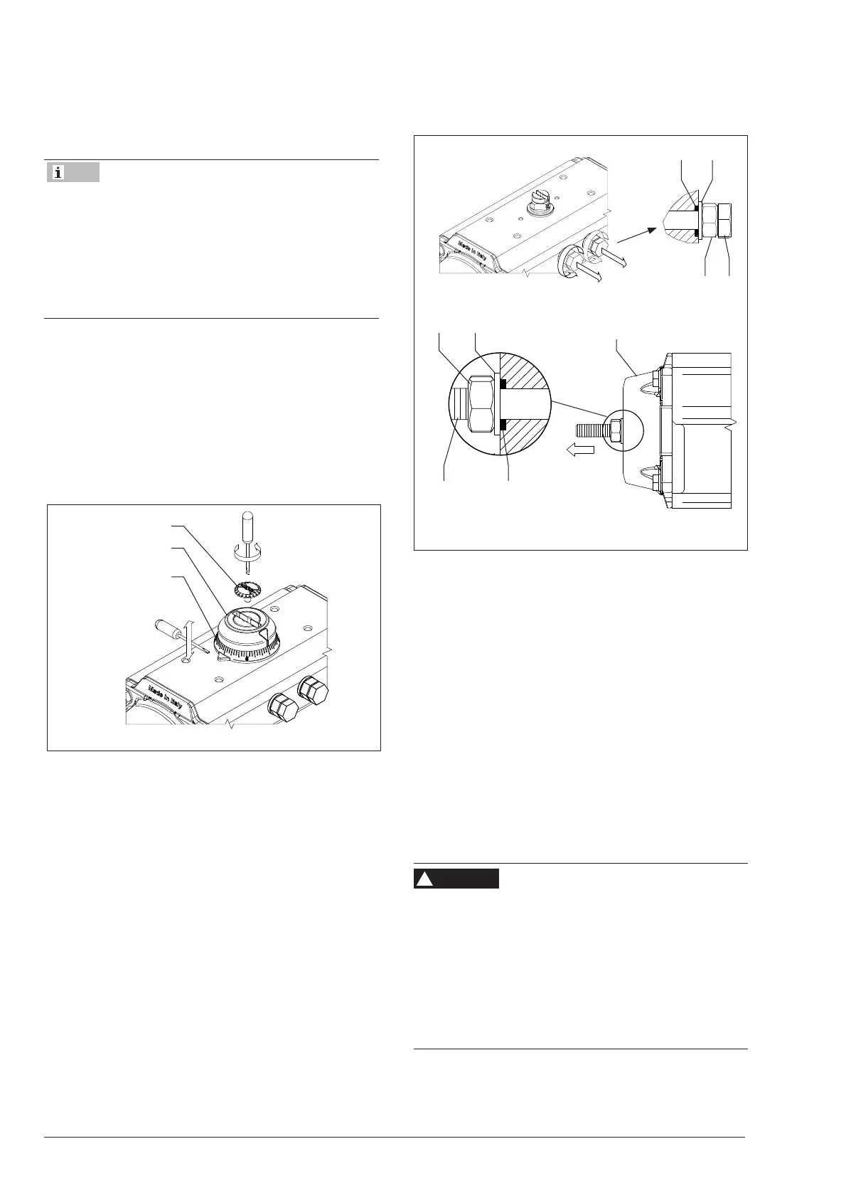
9.3.2 Stop cap screws removal
0204
0311
Fig. 9-3
221G
222G
11R
03R04R
30R
Refer to Fig. 9-1 and Fig 9-3.
− Remove both stop cap screws (02) together with nuts (04)
and washers (03).
− Remove the stop caps o-rings (11).
In case of actuator with extra travel stop adjustment (Fig. 9-3):
− loosen the nut (04R),
− unscrew partially the stop screw (221G/222G) out from
the actuator, making sure that the stop screw
(221G/222G) is not in contact with the piston anymore.
9.3.3 End caps disassembly
Refer to Fig. 9-1, Fig 9-4 and Fig 9-5.
Disassemble one end cap at a time.
Risk of personal injury due to compressed springs.
End caps are under tension due to compressed springs.
Î Before starting any work on the actuator disconnect all
pneumatic / hydraulic / electrical supplies from the actua-
tor and exhaust the pressure from the power module.
Î Make sure that the actuator is in the closed position (0°)
before disassembling.
Î Make sure that the stop cap screws (02) have been cor-
rectly removed as per section 9.3.2.
WARNING
!