Mounting Location
• The water flowing across the hull
must
be smooth with a
minimum of bubbles and turbulence (especially at high speeds).
Caution
: DO NOT MOUNT near water intake or discharge
openings or behind strakes, fittings, or hull irregularities.
• The multisensor
must
be continuously immersed in water.
• The transducer beam
must
be unobstructed by the keel or
propeller shaft(s).
• Choose a location away from interference caused by power and
radiation sources such as: the propeller(s) and shaft(s), other
machinery, other echosounders, and other cables. The lower
the noise level, the higher the echosounder gain setting that
can be used.
• Choose a location with a minimum deadrise angle.
• Choose an accessible spot inside the vessel with adequate
headroom for the height of the housing, tightening the nuts, and
removing the insert.
Model
Min. with fairing
B744V 255mm (10")
B744VL 381mm (15")
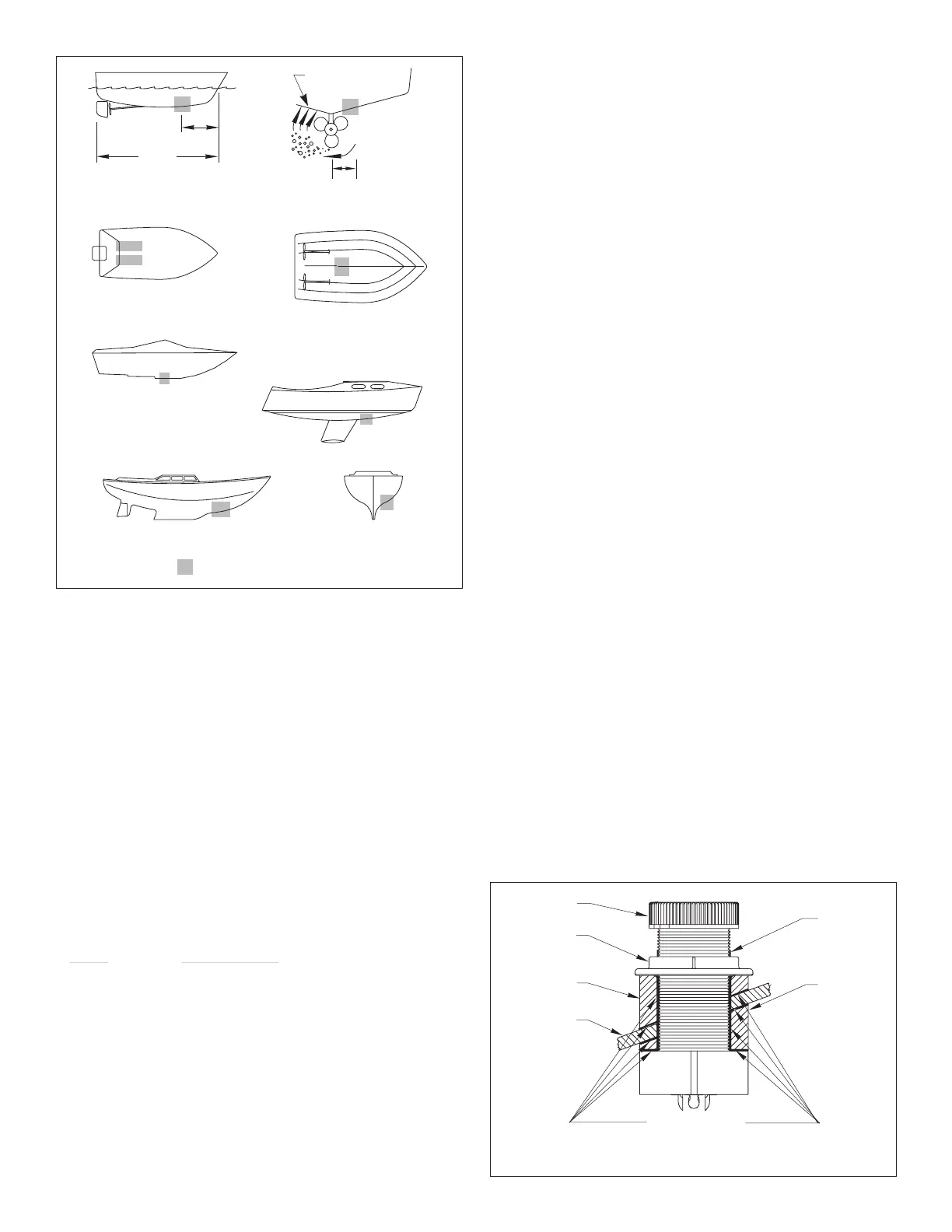
Hull Types
(see Figure 1)
•
Displacement hull powerboat
—Locate 1/3 aft LWL and
150–300mm (6–12") off the centerline. The starboard side of
the hull where the propeller blades are moving downward is
preferred.
•
Planing hull powerboat
—Mount well aft near the centerline and
well inboard of the first set of lifting strake
s to insure that it is in
contact with the water at high speeds. The starboard side of the
hull where the propeller blades are moving downward is preferred.
Outboard and I/O
—Mount forward and to the side of the engine(s).
Inboard
—Mount well ahead of the propeller(s) and shaft(s).
Stepped hull
—Mount just ahead of the first step.
Boats capable of speeds above 25kn
(29MPH)—Review
multisensor location and operating results of similar boats before
proceeding.
•
Fin keel sailboats
—Mount to the side of the centerline and
forward of the fin keel 300–600mm (1–2').
•
Full keel sailboats
—Locate amidships and away from the keel
at the point of minimum deadrise angle.
Installation
The following instructions are for a Standard Fairing ONLY.
WARNING
: The B744V and B744VL
must be installed with a
fairing (High-Performance or Standard). If the multisensor is
installed without a fairing, there is insufficient surface area
around the drilled hole to seal it to the hull. Water may leak
into the hull causing damage to the boat or possibly sinking.
WARNING
:
A High-Performance Fairing
must be installed
following the installation instructions that come with the fairing. The
High-Performance Fairing requires an anti-rotation bolt. Failure to
install the anti-rotation bolt may result in the fairing rotating while
the boat is underway. The effect may be violent movement and loss
of steering. This could result in serious injury or death to
passengers and/or damage to the boat or other property.
Cored Fiberglass Hull
—Follow separate instructions on page 5
Hole Drilling
Warning
: Always wear safety goggles and a dust mask.
1. Drill a 3mm or 1/8" pilot hole perpendicular to the waterline from
inside the hull (see Figure 2). If there is a rib, strut, or other hull
irregularity near the selected mounting location, drill from the
outside.
2. Using the 51mm
or
2" hole saw, cut a hole from outside the hull.
Be sure to hold the drill plumb
, so the hole will be perpendicular
to the water surface.
3. Sand and clean the area around the hole, inside and outside, to
ensure that the sealant will adhere properly to the hull. If there is
any petroleum residue inside the hull, remove it with either mild
household detergent or a weak solvent (alcohol) before sanding.
2
Figure 1.
Best location for the multisensor
inboard
pressure waves
1/3 aft
full keel sailboat
displacement hull
(6–12")
fin keel sailboat
150–300mm
LWL
(Load Waterline Length)
stepped hull
outboard and I/O
planing hulls
Copyright © 2005 Airmar Technology Corp.
marine sealant
stem
hull nut
backing
hull
Standard
Figure 2. Drilling and bedding
(B744V shown)
cap nut
block
Copyright © 2005 Airmar Technology Corp.
Fairing