Electrical installation
GasEye Cross Duct
73
Customer cable connection
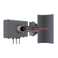
A separate electrical cable is connected via Power supply and I/O cable gland for
powering the analyzer and communication with the customer. Please use the cable
with minimum 12 x 0.5mm
2
wires and external diameter between 7-12 mm to fit into
the gland. Cable supplied by Airoptic is preferred. Please follow the step-by-step
instruction for correct installation.
Figure 77. Customer cable.
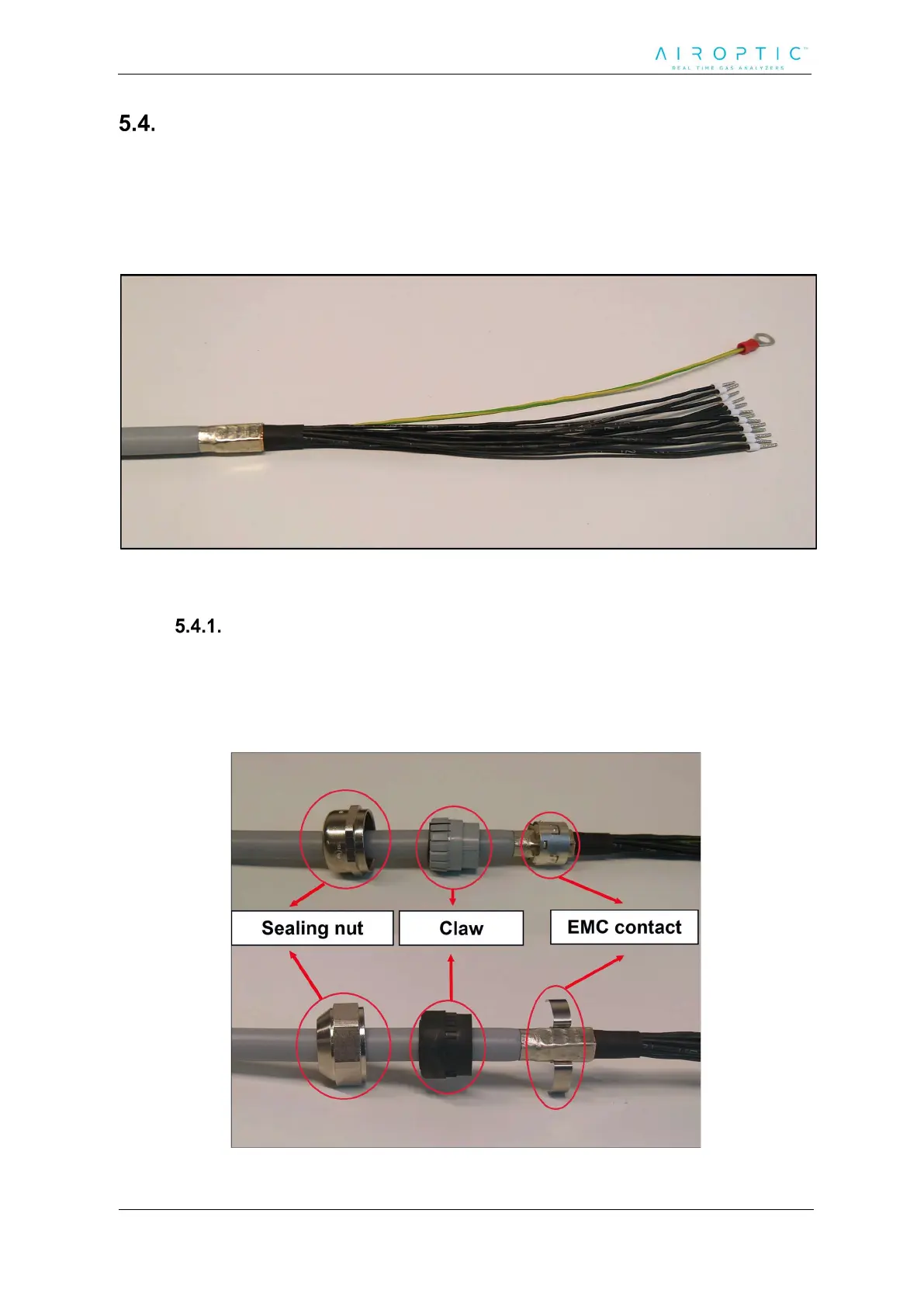
Customer cable installation instruction:
1. Cautiously dismount central unit housing lid by unscrewing each of the four
bolts.
2. Place the sealing nut and the claw on the customer cable.
Figure 78. Sealing nut and claw on the customer cable.
 Loading...