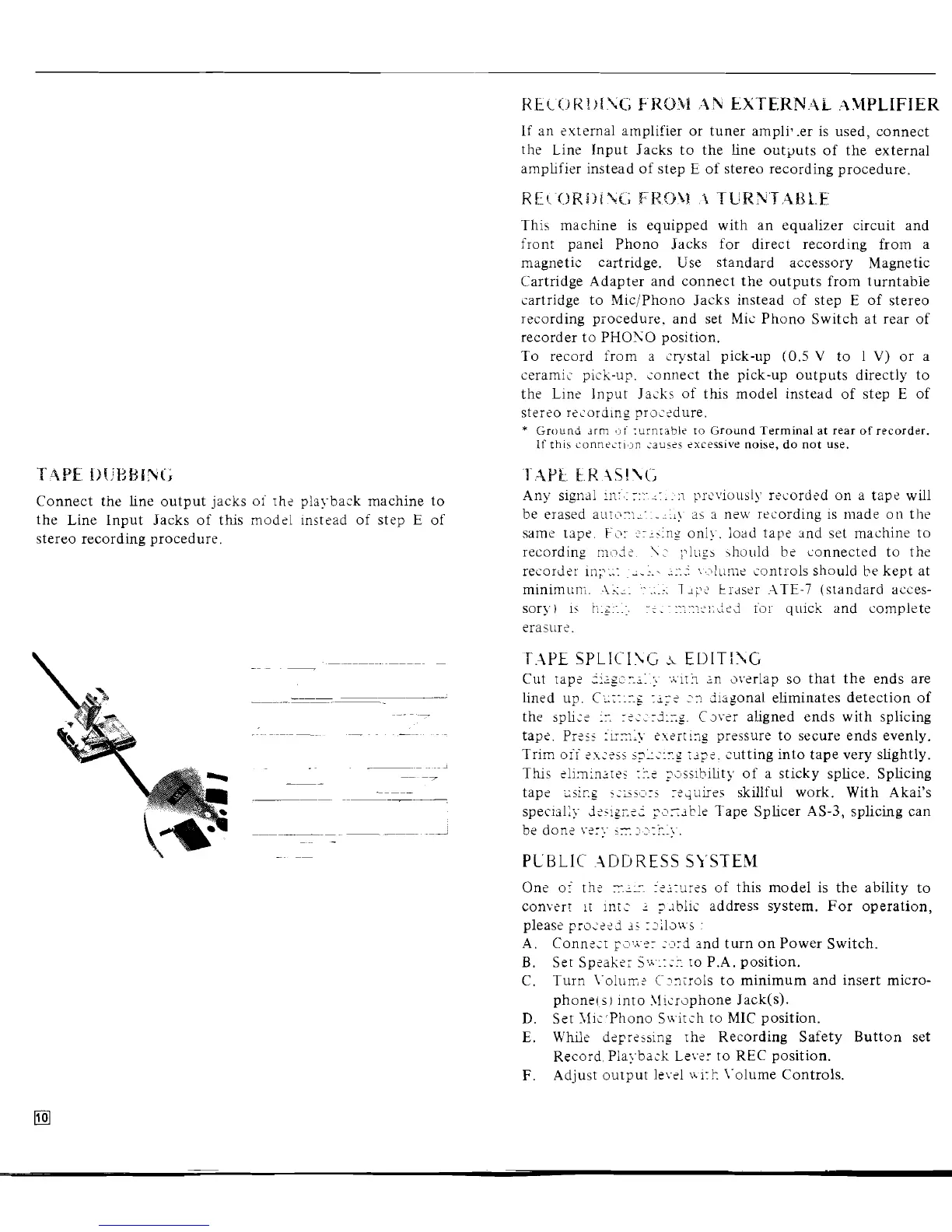
Connect the line output jacks ot rh? plal-back machine to
the
Line Input Jacks
of thls mod?l instead of step
E
of
stereo recording procedure.
KEciiKI:IfC;
FK09i
:2h
\r;>iTE;KN.-\i
:IMPLIFIEK
If an external amplifier or tuner ampli7.er is used, connect
the Line
Input Jacks to the line outputs of the external
amplifier instead of step
E
of stereo recording procedure.
This machine is equipped with an equalizer circuit and
front
panel Phono Jacks for direct recording from a
magnetic cartridge. Use standard accessory Magnetic
Cartridge Adapter and connect the outputs from turntable
cartridge to
Mic/Phono Jacks instead of step E of stereo
recording procedure. and set
Mic Phono Switch at rear of
recorder to PHONO positioc.
To record from a crystal pick-up
(0.5
V
to 1
V)
or a
ceramic pick-up. connect the pick-up outputs directly to
the Line Input Jacks of this model instead of step E of
stereo recording pro:-dure.
*
Ground
Jrrn
:u:ntabl? to
Ground Terminal at rear of recorder.
If
this
i'onn?zrl,>n
;~US~S
excessive
noise, do not use.
T.-IP~
F.F.
x~i~i;
Any signal
111.:
r::
:-.
:I
prcviousi!. recorded on a tape will
be erased
aura-:~--:11!
33
B
new recording is made on the
same tape.
Fc:
:;>ins
oni!. load tape and set machine to
recording
n~,.~,i:
\;.
;ll~i_~b
\11o~11d b? connected to the
..
.
recorder in;?:;:
L....
;...I
:.>lume controls should be kept at
minimuni.
-1:;;.
:.
7
17:
trdsei .IT€-7 (standard acces-
sor).) is
t;.~.:.:.
r,.
~
::.::-.:::,ifJ.
for
quick and complete
erasur?.
P.I\PE
SPLICI\G
.i
EDITI$C
Cut rap?
5ig~c;:
..iirh
n
dvfrlap so that the ends are
lined up.
C;:rr:rg
1.i;:
-2
diagonal eliminates detection of
the
jph;:
;L
r?c_rJ::g. Csvfr aligned ends with splicing
tape.
Pr:si
:~-rn:y
exeir!n pressure to secure ends evenly.
Trim
oii :I,-sss s?L::rg rjp:. cutting into tape very slightly.
Ths ~1imin;res
r.:
?;#ss~bility of a sticky splice. Splicing
tap?
2sir.g
i:sis:sri
r:;airei
skillful work. With Akai's
special:>-
;i;.i~g.-,t
?szjbl? Tape Splicer AS-3, splicing can
.
.
be don?
vzr;
57.
Ilzrr..).
PUBLIC .I\DDRESS
SI'STEM
One of th:
rr:-
I:irur?s of this model is the ability to
converr
it
lni?
r
?.~blic address system. For operation,
please
pro;:-3 3s rl';lsa-s
:
A.
Conn:;r ~2,zsr :'1rd and turn on Power Switch.
B.
Set Spzake; 5;~:::: ro P.A. position.
C. Turn
i-oltirr,;. C2nirols to minimum and insert micro-
phone(
SJ
into .\!!crophone Jack(s).
D.
Set Jlic'Phono Sairch to MIC position.
E.
U'hlle d?pr?sjing rh? Recording Safety Button set
Record, Playback
Lev?: to REC position.
F.
Adjust output level v\i:k \-olume Controls.
 Loading...