2.
DESCRIPTION
OF
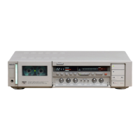
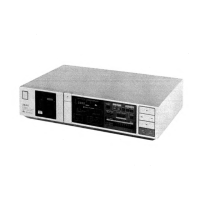
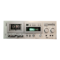
GX-F71
AUTO TUNING FUNCTION
1) When, after the power
is
"on",
the cassette-pack
is
set and the test key
is
set to
"on"
position, termi-
nals,
@,
® and ,
of
tuning CPU (IC
l)
be-
comes
"L",
"L"
and
"H",
respectively, system
control (IC8)
is
set to FF mode and the
counter
quickly winds 64 counts. Then, , ® and ®
becomes
"H",
"L"
and "L", respectively, the
syscon CPU
is
set
to
Rec/Play mode and the bias
circuit oscillates.
2 Coarse adjustment
of
level
Terminals ,
® and @
of
tuning CPU
(ICI)
becomes
"L",
"L",
and
"L"
respectively when
CPU
is
set to Rec/Play mode and the test signal
OSC
oscillates 1 kHz. This
output
passes through
the PRE-Amp circuit, enters terminal
®
of
IC3
as
the test signal and
is
output
from
@.
Then, the
signal passes through Rec Amp, mixed with the
bias and
is
applied to the REC head.
The 1 kHz signal recorded on the tape passes
through the
PB
Head and
PB
Amp, Leh and Reh
signals are selected by the switch circuit
of
TR23,
24 and
34
(Tuning P.C Board), A/D converted at
IC8
and IC3 (Part) and, then, input into ICI as
a
PB
signal level detection signal.
Under this condition, the signal level
of
I kHz
is
positively half-wave rectified by IC8 and charged
to C35
(I0µ/16V)
and applied
to
IC3 ®,
but
5 bits
(32
steps)
of
stair step waveform signal is
applied to the terminal,
[C3
CD,
and when the
level
of
IC3
becomes equal
to
that
of
terminal
®,
the
output
is
changed from
"L"
to
"H"
while
the collector
of
TR49
is
trailed from
"H"
to
"L".
PB
signal level
is
detected by this trailing. At this
time, the data outputs at terminals
®,
® ,
®,
® and
of
ICl are written as level data in latch
(1)
of
IC3. This operation is performed once for
Leh and Reh, respectively.
3)
Bias adjustment
When the coarse level adjustment
is
completed, a
step form wave (up direction)
is
output
from
IC3
(Leh) @ terminal and controls IC7 ®
➔
IC7
©
➔ TR19, thus changing the amount
of
bias.
As
the bias
is
changed, the signal
of
I kHz from
the test signal circuit
is
recorded
on
the tape
as
a signal
of
changed level and accordingly the
PB
level
is
changed. Since these changes are in
proportion
to the bias change, the
PB
level
is
detected.
The bias
is
adjusted twice; in
up
direction and
down direction, therefore, the mean value added
+4
step is written
as
bias data
into
the latch
of
IC3
(Leh)
as
the most suitable bias amount. Only Reh
is
subjected
to
bias adjustment.
4) l kHz level adjustment
When the bias adjustment
is
completed, the l kHz
level adjustment
is
made
in
the same manner
as
the coarse level adjustment.
5) 7 kHz EQ adjustment
When
the
I kHz level adjustment
is
completed,
terminals
CD,
® and @
ofICI
become
"L",
"H"
and
"L",
respectively and the test signal
OSC
circuit oscillates 7 kHz. The inner D/A
(2)
and
latch
(2)
of
IC3 are controlled by the 5 bit signal
from CPU
(ICl)
so that the 7 kHz
PB
level is
adjusted
to
the same level
as
the l kHz reference.
When the 7 kHz level
is
adjusted
to
the same level
of
I kHz reference, the data are written into latch
(2).
The 7 kHz EQ adjustment
is
made once in Leh and
Reh, respectively.
6)
13
kHz EQ adjustment
After 7 kHz EQ
is adjusted, terminals , ® and
@
of
ICI become
"H'',
"H"
and
"L",
respectively
and the test signal
OSC
circuit oscillates
13
kHz
and when the
PB
signal level
of
13
kHz
is
adjusted
to the same level
as
the 1 kHz reference level, the
data
of
13 kHz
EQ
are written into latch (3)
of
IC3.
The adjustments from
4) to 6) are repeated three
times.
7) When the above tuning
is
completed, terminals
@,
® and ®
of
ICl
become
"L",
"H"
and
"H",
respectively
and
the syscon
CPU
is
set
to
RWD
mode.
In case
of
TUNING REC, the tape cot1nter
is
rewound to "O'' and in case where Rec/Play and
Timer
Start
SW
are off,
REW
is
chan_ged
to
REC/PAUSE
at
"23"
on the counter.
1-3
 Loading...