Description of the Receivers 9 (36)
Sesam 800 Operating Manual Document-ID: 941211-000
Version: D1 Author: SH
5 Description of the Receivers
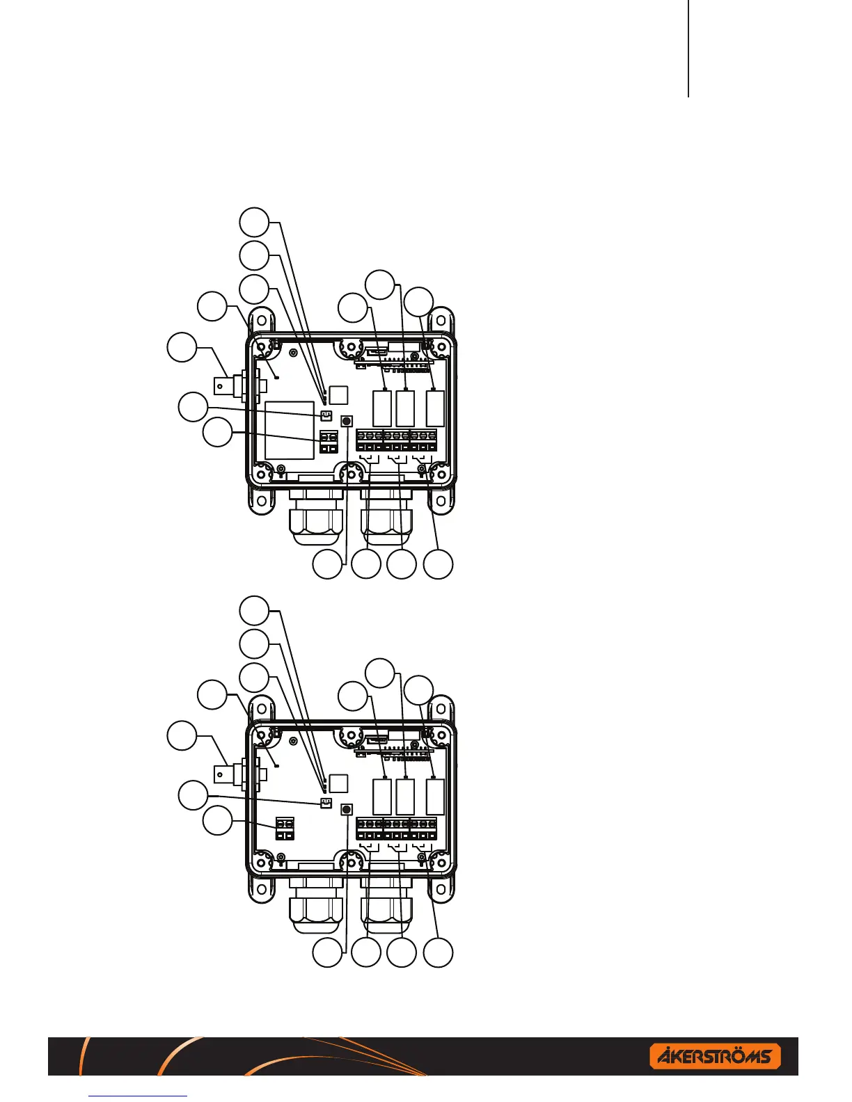
1
2 3
4 5
6
7 8 9
R1
R2
R3
4
5
6
7
1
2
3
8
9
14
10
11
12
13
Figure1.Sesam 800 RX 230 V AC
model indicators, connections
andjumper.
1.LED1Relay1status
2.LED2Relay2status
3.LED3Relay3status
4.LED4Power
5.LED5Squelch
6.LED6Status
7. LED 7 Learn
8.Powerconnection230VAC
9.JumperJ1HighSecurity
TransmissionModesetting
10.Learn/Erasebutton
11.Connectiontorelay1
12.Connectiontorelay2
13.Connectiontorelay3
14. Antenna connector
1
2 3
4 5
6
7 8 9
R1
R2
R3
4
5
6
7
1
2
3
8
9
14
10
11
12
13
Figure2.Sesam 800 RX 12-24 V DC
model indicators, connections and
jumper.
1.LED1Relay1status
2.LED2Relay2status
3.LED3Relay3status
4.LED4Power
5.LED5Squelch
6.LED6Status
7. LED 7 Learn
8.Powerconnection12-24VAC/DC
9.JumperJ1HighSecurity
TransmissionModesetting
10.Learn/Erasebutton
11.Connectiontorelay1
12.Connectiontorelay2
13.Connectiontorelay3
14. Antenna connector
 Loading...