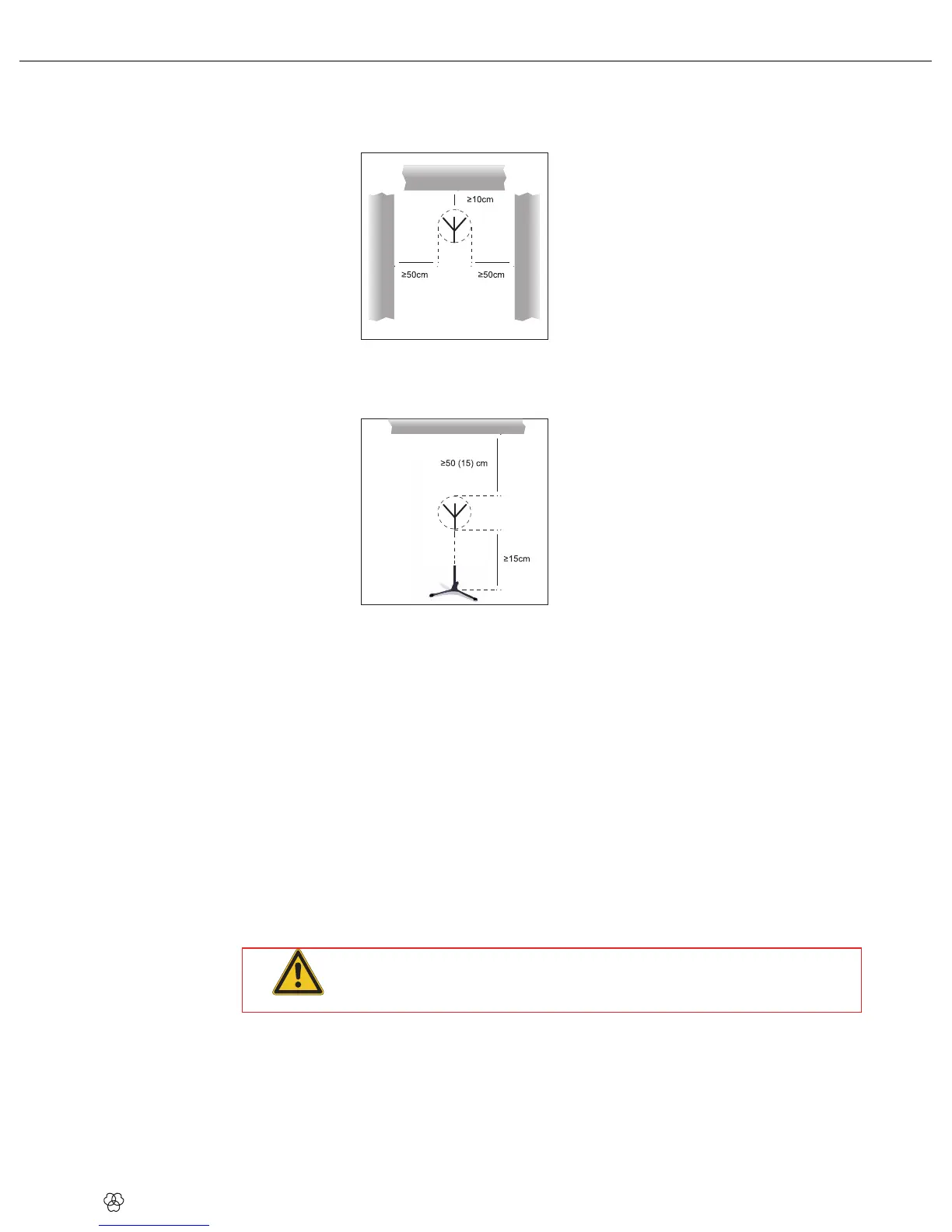
Wall/Ceiling Mounting
If you mount your antennas on a wall or ceiling, be sure to keep the following minimum
distances:
Fig 4: Min
imum distances from plane surfaces
Mount the antenna at least 10 cm (4 in.) in front of and at a minimum lateral dist
ance of
50 cm (20 in.) fr
om any walls or other plane surfaces, metal grids,
or metal scaffolding.
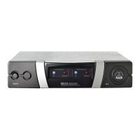
Fig 5: Min
imum distances from floor and ceiling
Make sure the antenna will sit at least 15 cm (6 in.) above the floor or 50 cm (20 in.) from the
ceiling (or 15 cm (6 in.) if you route the cable to the antenna from above).
Single-channel System w
ith Passive Antennas
1)
Measure the cable run between the receiver and each antenna.
2) Refer to Table 1 on page 27 to find out whether you will need t
o
break the cable run
down into severa
l cables and insert one or two AB4000 antenna boosters. Table 1 states
the maximum acceptable cable lengths for RG58 and RG213 cabl
es separately.
3) Connect an antenna cable to each antenna.
4) Referring to Table 1, connect the antennas to the
antenna inputs on the receiver. If you
need one or two AB4000 antenna boosters, you will need to inse
rt an ASU4000 remote
power adapter between the receiver and the first antenna booster.
5) Check that the AC mains voltage stated on the power supplies for the ASU4000 and the
receiver is identi
cal to the AC mains voltage available where you will use your syst
em.
Using the power
supplies with a different AC voltage may cause damage to the unit.
6) Connect the remote power adapter and the receiver to their respective power su
pplies
and connect each power supply t
o a convenient po
wer outlet.
ATTENT
ION
Using the power supplies with a different AC voltage may cause damage to the unit.
Single-channel System with Active Antennas
1) Measure the cable run between the receiver and each active antenna
.
2) Refer to Table 1 on page 27 to find out whether you will need t
o
break the cable run
down into severa
l cables and insert one or two AB4000 antenna boosters. Table 1 states
the maximum acceptable cable lengths for RG58 and RG213 cabl
es separately.
3)
Connect an antenna cable to each antenna.
Connecting An
tennas