60
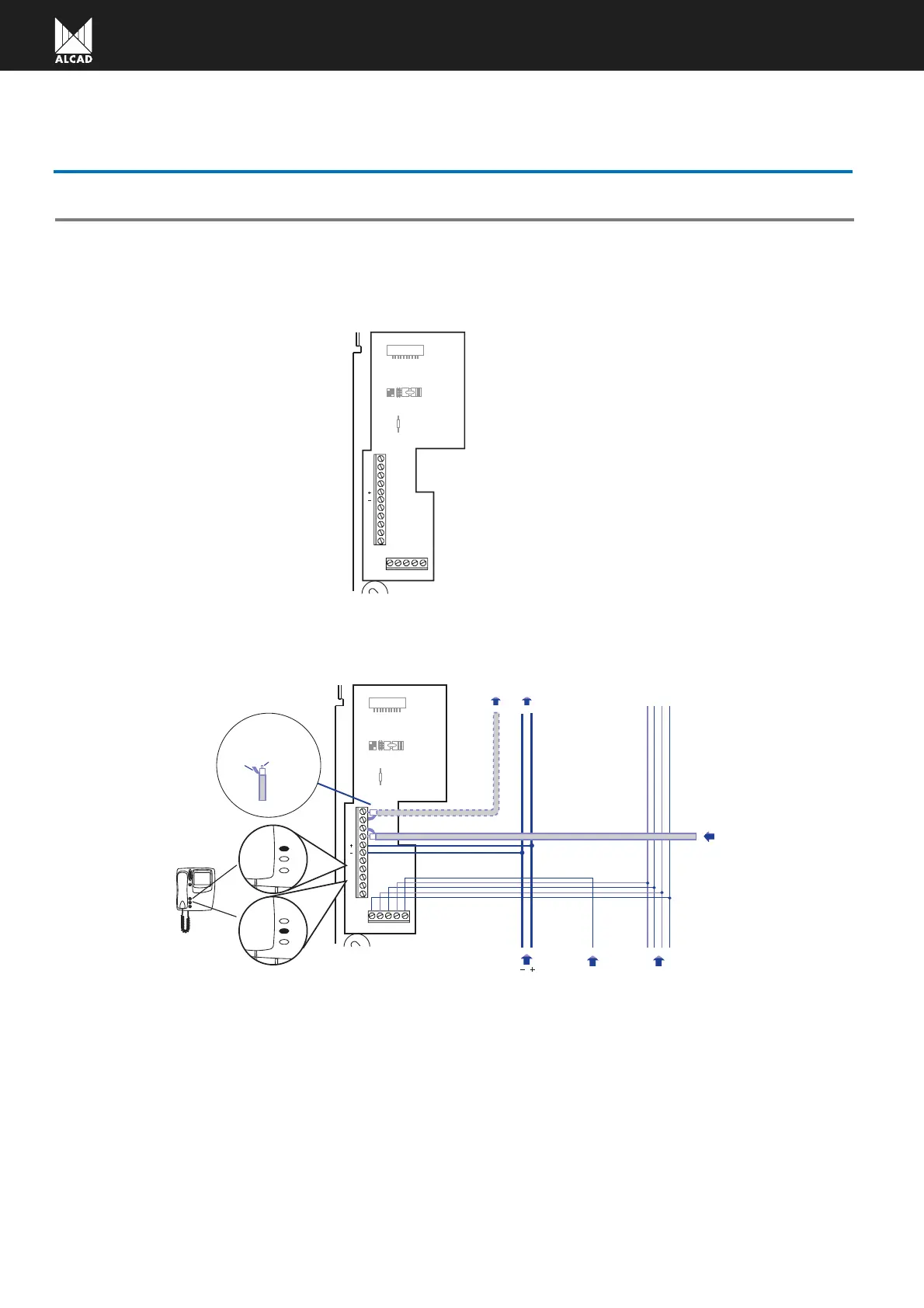
CONNECTIONS BRACKET
CONNECTIONS
12 345
V1
V1
25
26
27
28
24
R1
CC1
AB
M
M
J1
Electronic call
5
Loudspeaker
4
Microphone
3
Common terminal
2
Lock release
1
Video signal common
M
Video signal
V1
26
25
Auxiliary push-button (P1)
24
27
Power supply
+
Power supply ground
-
Important:
Terminals number 24, 25, 26 and 27 are potential-free contacts
Connection limitations: 50 mA@12 Vdc
Monitor connector
CC1
Auxiliary push-button (P1)
Auxiliary push-button (P2)
Auxiliary push-button (P2)
Video signal input
12 345
V1
V1
25
26
27
28
24
R1
CC1
AB
M
M
J1
Audio unit
Call
Push
Button
4321
Power supply
V1, M
Next monitor
(Installation in serial or in parallel)
-, +
P1
P2
Internal
conductor
Mesh
COAXIAL
CABLE
Make the terminal connections as shown. Use the guides of the bracket to pass the connection cables. For more infor-
mation consult the installation wiring diagrams at the back of this manual.
Wiring diagrams:
Description of terminals:
 Loading...