61
ADJUSTMENT
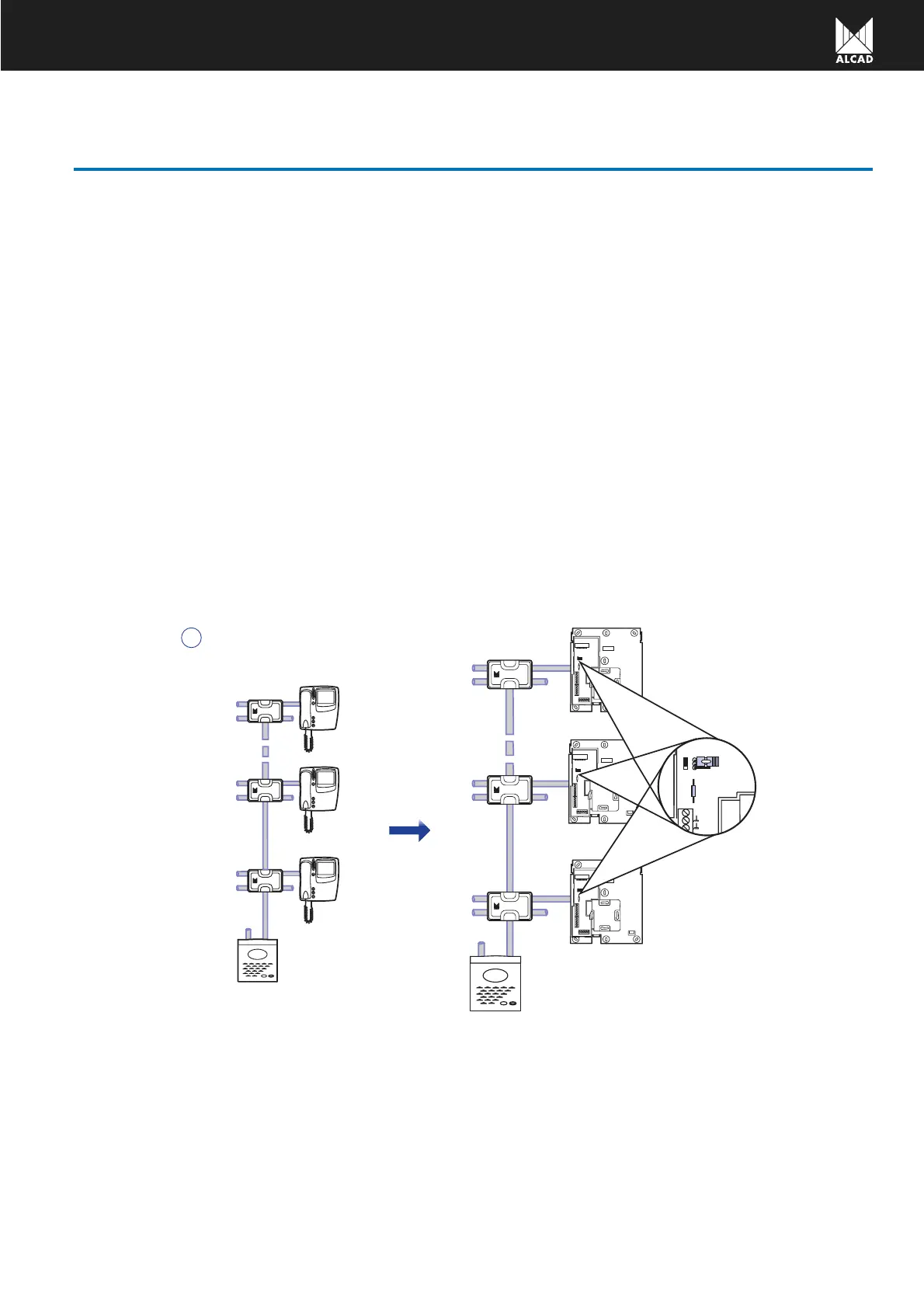
Configuration of the J1 bridge (tap-off feed)
In installations where the distribution of the video signal is carried out through tap-offs the tap output of the corres-
ponding tap-off should be fed through the coaxial cable so the monitors can receive the signal captured by the video
unit.
The J1 bridge allows the configuration of the connections bracket to send the necessary voltage through the coaxial
cable for these cases.
Place the J1 bridge in position B if the video signal for the house or flat comes from a tap-off. If not, leave it in posi-
tion A.
Configuration of the 75Ω end of line resistance R1.
It is important that the video line is charged with 75
Ω. on the last monitor to ensure optimum quality of image.
To do so proceed as follows:
If the distribution of the video signal is made in a star-shaped pattern then leave the 75
Ω on the monitor of each
house or flat. If there are several monitors within one particular house or flat associated in parallel to the same call line,
remove all the resistances except the one on the monitor which is at the end of the line.
In serial mounting installations cut the 75
Ω resistance on all the monitors except the one at the end of the line.
The following examples show the configuration of the J1 bridge and of the R1 resistance in terms of the type of the installa-
tion.
DIV-024
DIV-024
DIV-024
DIV-024
DIV-024
DIV-024
A
 Loading...