64
GENERAL POINTS CONCERNING INSTALLATIONS
DIAGRAMS
6
Remember to protect the power supply units of the ins-
tallation in compliance with the existing requirements
governing electrical installations (keep away from mag-
netic fields, high temperatures, ensure correct fusing,
etc.).
It is recommended to make the distribution of the video
signal with the use of tap-offs and splitters.
In video door entry systems the coaxial cable line of
the installation should be charged with 75
Ω. The tap-offs
and the connections brackets include a 75
Ω end of line
resistance.
To ensure the correct functioning of the electronic video
door entry system it is essential that the appropriate sec-
tions of cables are used. Two factors directly affect the
section of the cable which should be used; the distance
between the different elements of the system and the
number of monitors and/or telephones associated to the
same call line (maximum 4 devices). If there are several
monitors or telephones associated to the same call line it
will be necessary to increase the thickness of all the
cables of the installation in proportion to the number of
devices, in the following manner:
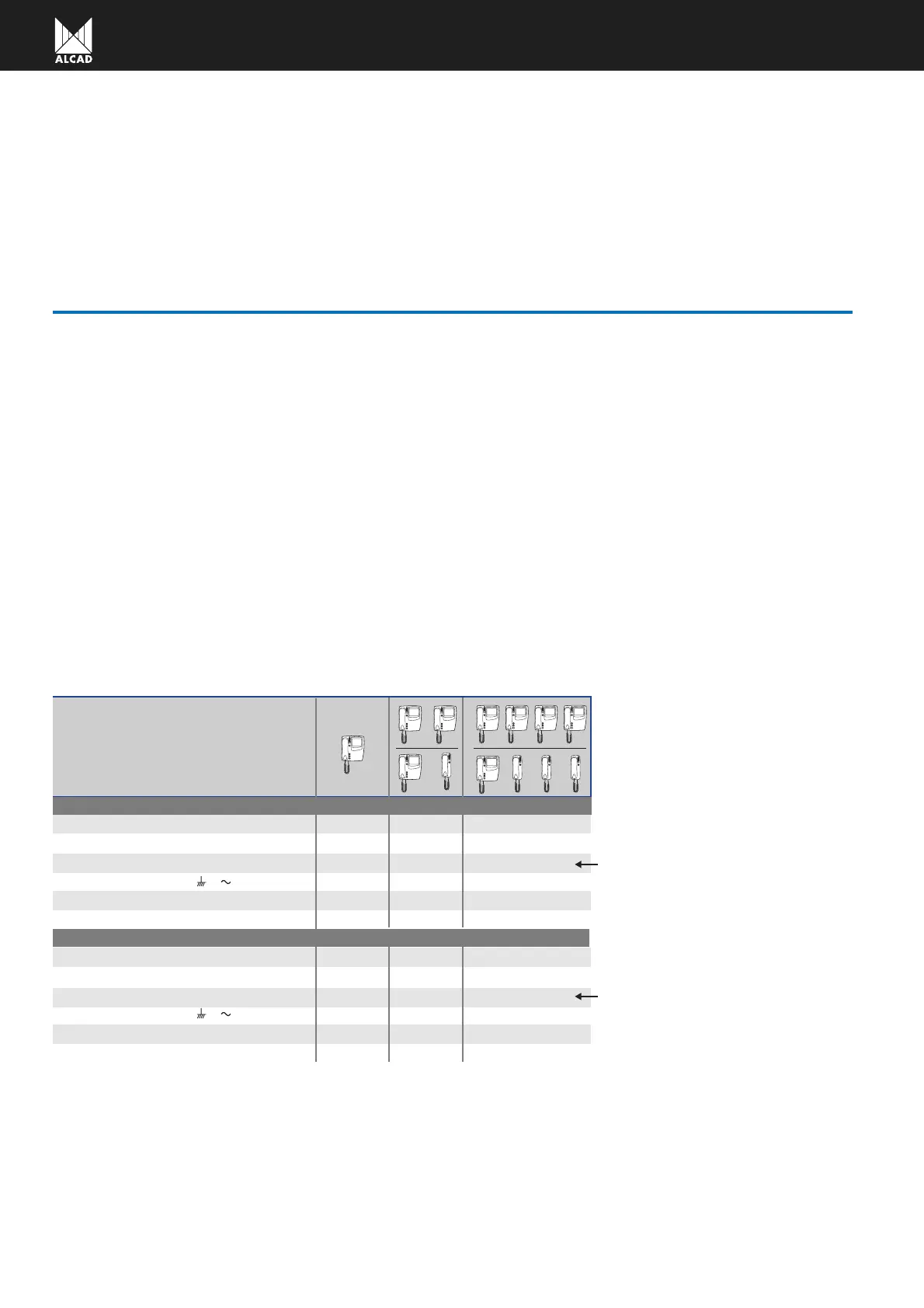
Devices
per
flat/house
Up to 100 metres
0,25 mm
2
1 mm
2
75 Ω
ommon wires and call wires to monitors (1,2,3,4,5)
ires of union between panels (16,17,18)
ower supply wires to monitors (-,+)
ower supply wires to panel ( ,
V ,-)
lectric lock wires (11,12)
oaxial (V,M)
1 mm
2
1 mm
2
0,25 mm
2
x 2
x 2
x 2
x 4
x 4
x 2
1 ALM-040 for every 2 monitors
Up to 200 metres
2,5 mm
2
0,5 mm
2
x 2
x 2
x 2
x 4
x 4
x 2
0,5 mm
2
2,5 mm
2
2,5 mm
2
1 ALM-040 for every 2 monitors
ommon wires and call wires to monitors (1,2,3,4,5)
ires of union between panels (16,17,18)
ower supply wires to monitors (-,+)
ower supply wires to panel ( ,
V ,-)
lectric lock wires (11,12)
oaxial (V,M)
75 Ω
 Loading...