EasyManua.ls Logo

Alcatel-Lucent OmniPCX Office RCE Small User Manual

Alcatel-Lucent OmniPCX Office RCE Small
238 pages
To Next Page IconTo Next Page
To Previous Page IconTo Previous Page
Page #124 background image
4.7.1 Hardware description
4.7.1.1 Overview
The V24/CTI Interface Module allows a Data Terminal Equipment (DTE) to be connected to
the OmniPCX Office, via a UA link, by means of an RS232 serial link (CTI port) or a V24 link.
The V24/CTI Interface Module can be used alone or combined with an Alcatel-Lucent 9 series
set.
The V24/CTI Interface Module replaces the 4093 PLUGWARE V24/CTI. The two interface
modules can operate together: a data link can be set between an V24/CTI Interface Module
Interface Module and a 4093 PLUGWARE V24/CTI.
Note:
The V24/CTI Interface Module is also compatible with UA 3G sets.
CTI port
The RS232 serial link carries signalling (up to 9600 bit/s) and allows telephone operations
such as call management and call monitoring. The audio part is carried out by the associated
dedicated set.
V24 port
The V24 port is considered as a DCE and provides a capacity of 19200 bit/s (ECMA 102) for
an asynchronous V24 transmission. The electrical interface complies with the V28
recommendation of the CCITT.
Figure 4.48: V24/CTI Interface Module Configuration Example
4.7.1.2 Compliant Standards
4.7.1.2.1 Safety Requirements
- EN60950: European requirements
- UL 1950: US requirements
- CAN/CSA-C22.2 No 950-95: Canada
Chapter
4
  &'(
4-76
     

Table of Contents

Question and Answer IconNeed help?

Do you have a question about the Alcatel-Lucent OmniPCX Office RCE Small and is the answer not in the manual?

Alcatel-Lucent OmniPCX Office RCE Small Specifications

General IconGeneral
UsersUp to 50
Maximum Users50
SIP Trunks SupportedYes
VoIP Protocols SupportedSIP, H.323
IP TrunkingYes
Storage Temperature-20°C to 70°C
TypeIP PBX
Target MarketSmall Businesses
VoicemailIntegrated
IP Phones SupportedYes
Management InterfaceWeb-based, CLI
Physical Dimensions440 x 44 x 280 mm
Power Supply100-240V AC, 50-60Hz
Operating Temperature0°C to 40°C
Relative Humidity10% to 85% non-condensing

Summary

Chapter 1 General Presentation

1.2 Security

Information regarding security aspects, safety rules, and declarations.

1.3 Protection against Interferences

Guidelines and procedures for preventing and mitigating interference.

Chapter 2 Hardware: Platform and Interfaces

2.4 Equipment

Information about available hardware boards and optional components.

Chapter 3 System Services

3.1 Software Licence Management

Management of software licenses, modes, and features.

3.2 Software Keys

Explanation of software keys, their types, and management.

Chapter 4 Installation and Cabling

4.2 Connections and Cabling

Detailed descriptions and diagrams of system connections.

4.3 Power Supply

Procedures for installing and connecting power supplies and batteries.

4.4 SIP Terminals

Installation and commissioning procedures for SIP terminals.

4.7 V24/CTI Interface Module

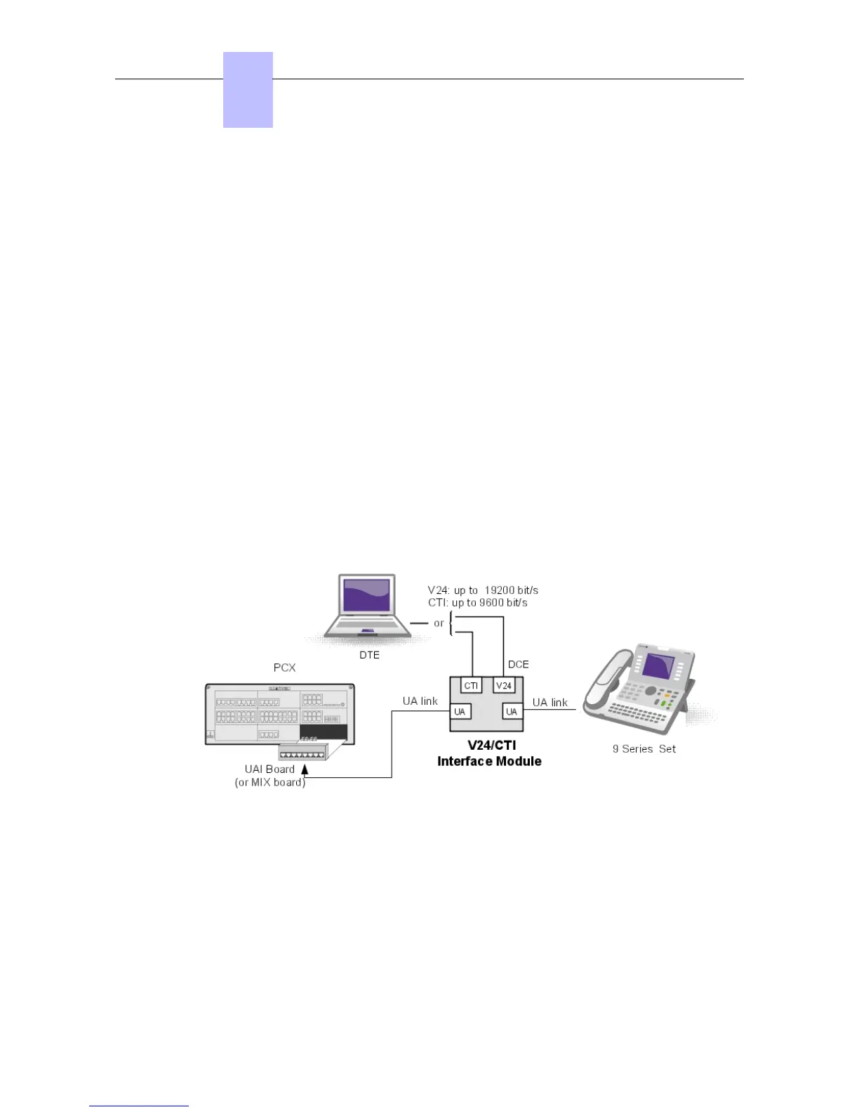
Hardware description and connections for the V24/CTI module.

4.8 AP Interface Module

Hardware description and connections for the AP Interface Module.

4.9 S0 Interface Module

Hardware description and connections for the S0 Interface Module.

4.10 Intelligent Base Stations

Installation, configuration, and safety recommendations for base stations.

4.11 IP-DECT Base Stations

Detailed description and connection of IP-DECT base stations.

Chapter 6 Start-Up

6.1 System Startup from a Phone Set

Procedure for starting and configuring the system using a phone set.

6.2 System Startup from OMC

Procedures for starting and configuring the system using OMC.

Chapter 7 Maintenance Services

7.1.1 Maintenance

Detailed maintenance procedures for hardware.

Related product manuals