MicrowaveradiorelaylinkZENITH80
17/52 1.2
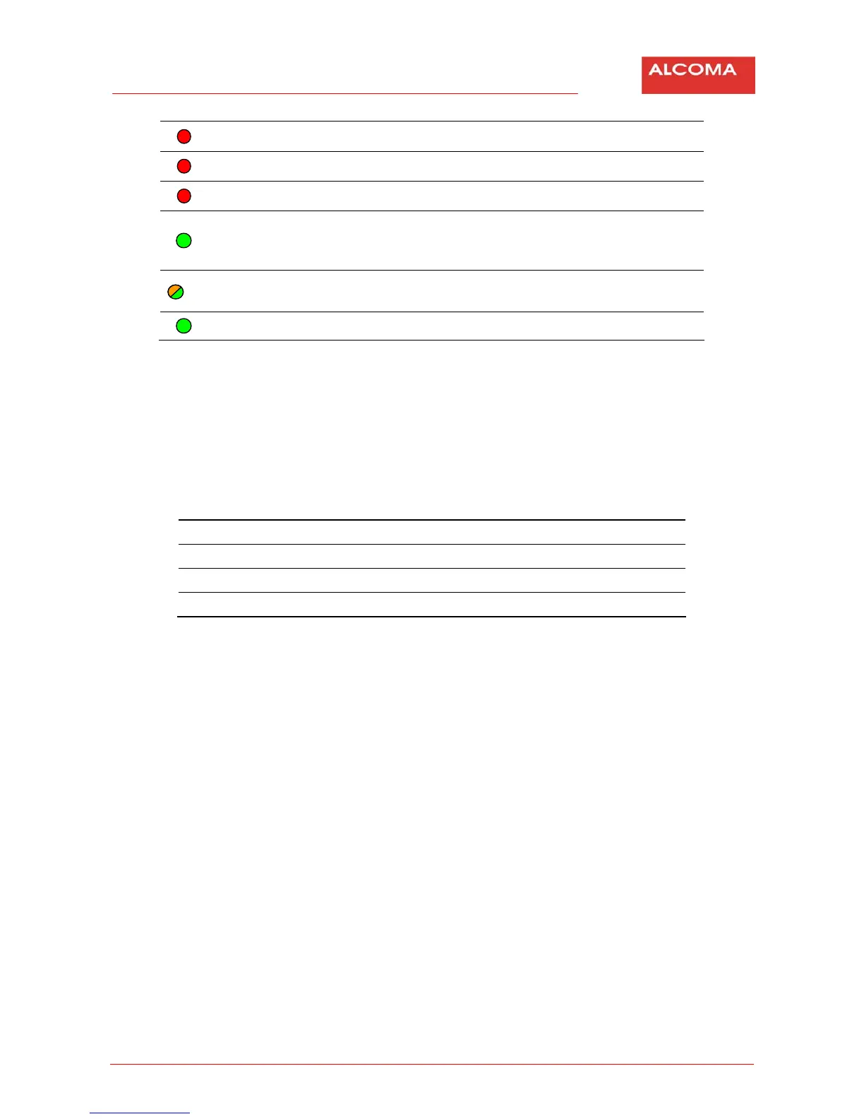
R
RXLEVELLOW Lowleveloftheinputmicrowavesignal
R
HIGHBER Increasederrorsonthemicrowavepath
R
FRAMELOSS Lossofframesync
G
OK
Blinks=monitoringsystemdoesnotregisteranyerrorstatesat
themoment.Lighton/Lightoff=monitoringsystemindicates
anerrorstate
YG
SFPLink/
Activity
Orange=LinkonSFP.Green=activity
G
Power
Indicationforstableoutputvoltageof+3.3V
Table6 MeaningofLEDsintheODUuserspace
Rotaryswitchfunctions
Therotaryswitchislocatedonthemotherboard.ItisaccessibleafterflippingoffthelidontheODU
cover.Thestationdoesnothaveanyotherelementsthatcanbechangedduringnormaloperation.
Position Description
0 Normalstatio noperation
1 Pointing
2÷F Reserve–notusedyet
Table7 DescriptionoffunctionsoftherotaryswitchintheODUuserspace
The rotary switch in the position Pointing (1) also switches off a transmitter of the local station.
Switching off of the output also in the remote station by the rotary switch can be used to find a
level of
interferencesignals(backgroundnoise)ongivenchannels.
The ZENITH 80 station is optimally tuned during manufacture, set and tested in accordance with
guaranteedparametersandcustomerrequirements.Ifthereisanewrequirementtoretunetoadifferent
channel or for a configuration change (possible on this equipment)
after installation or inspection, it is
possibleto dothis work usingthe monitoringprogram only. Retuning toa different frequencyrangethat
requiresreplacementofmicrowavefilterscanbedoneatthemanufactureronly.