MicrowaveradiorelaylinkZENITH80
19/52 1.2
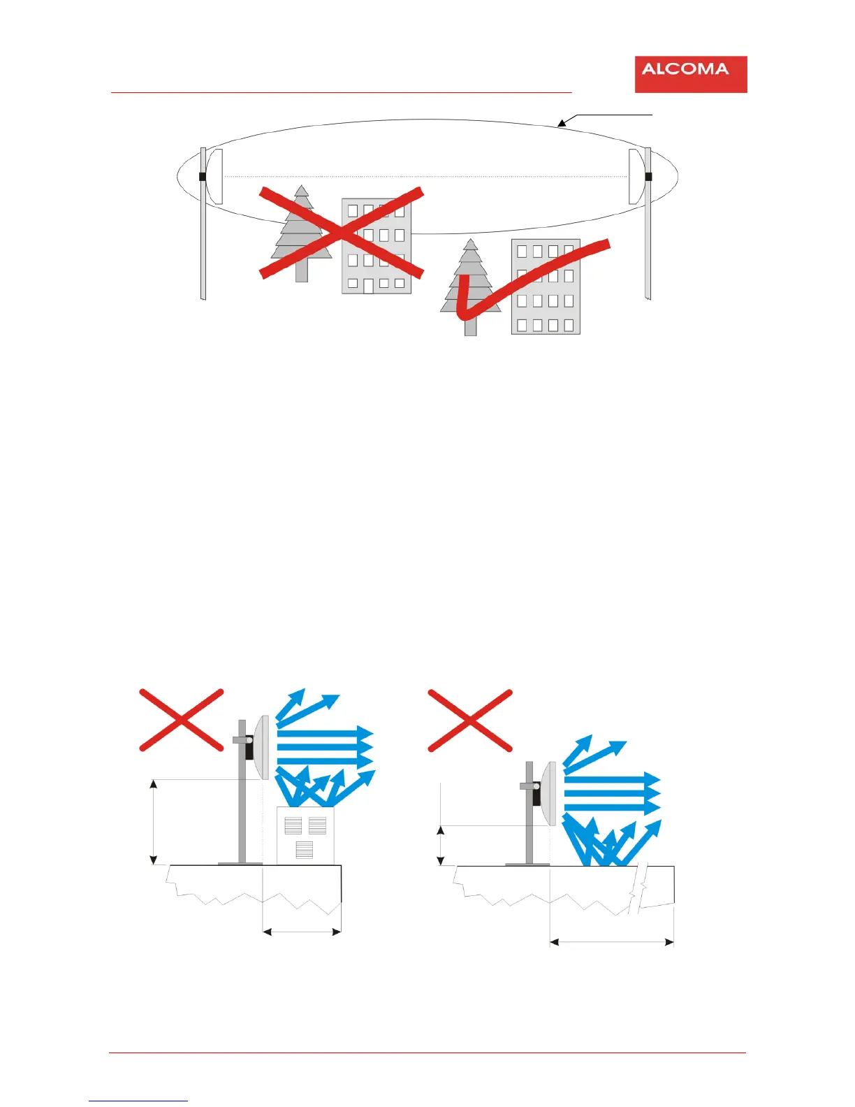
Figure9 TheFresnelzone
Figure 10 shows situation when a solid object penetrates a Fresnel zone of signal propagation. The
obstacle,justliketheoneonthefigure,causesbendingofthebeamalongthesharpedge.Thisbeamthen
arrivesatthereceiverantennalittlebitlaterthan
thedirectbeam.Inother wordstherearetwoidentical
signalscomingtotheantenna,butwithvariousphases,whichstronglydegradesthesignalquality;andthis
can cause temporary break in data transmission. Trees or other “soft” objects infringing on the Fresnel
zoneattenuate the radio signal.In short: The
fact that you canseethe oppositeside does notmeanthat
youcansetupaqualityradiolink.
3.3 PLACEMENTOFTHEANTENNAONASUPPORTCONSTRUCTION
Theantenna ofradiolink mustbeplacedsufficientlyfarawayfromotherantennas,inordertoavoid
undesirableperturbationofradiosignal.Badlyinstalledantennawillcausedeteriorationofourtransmitted
signal and also of the signals of neighboring links. During installation of a radio relay link we need to
calculate with adistance from the roof edge or different obstacles that can be present on the roof (A/C,
elevator shaft…). The following figures show incorrect and correct ways of installation of radio relay link
antennaonthesupportingconstruction.
Figure10 IAPRoperplacementofantennaonmountingpipe
Fresnelzone
Lineofsight
1,4m
0,3m
Roofline Roofline
1,3m
Morethan0,3m