EasyManua.ls Logo

Alcoma ZENITH 80 - Page 8

Default Icon
54 pages
Print Icon
To Next Page IconTo Next Page
To Previous Page IconTo Previous Page
Loading...
MicrowaveradiorelaylinkZENITH80
8/52 1.2
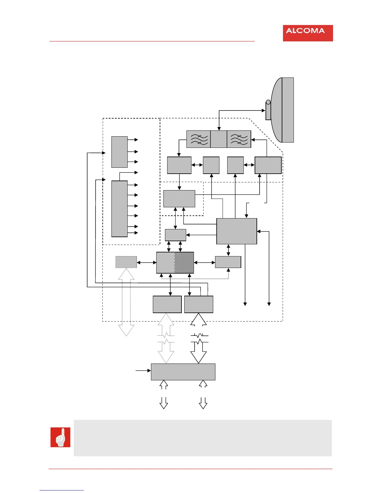
A received signal from the parabolic antenna is led through the diplexer to the receiver. There it is
amplified and mixed to the intermediate frequency of 3.75 GHz and further amplified. From there the
signalgoestoamodem.
Figure1 TheblockschematicoftheZENITH80link
CAUTION
UseonlyprotectedterminalboxmarkedALS1GEth(121/516*29)orALS12GEth(121/516*30)
forZENITH80link.
Thereisdangerofequipmentdamageincaseusingotherterminalbox.
MW
Powersuply
Motherboard
Line3+M
g
mt
Power=48V
(36÷72V)
ALS1x
DC‐DCconverter
=48V
Interconnecting
cables
Surge
protection
Muldex
Modem
DBPSK
µP
MW
receiver
MW
transmitter
PLL PLL
12V
Z
p
ráva
+12V
+5V
+3
,
3V
+2
,
5V
5V
Udet
Interface
RS232C
RSSI
Line3
Line2
Surge
protection
Diagnosti
100
SFP
10/100/1000
GEthswitch
100
Line3+power
DCDC
converter
+8
,
8V
+5
,
5V
5V