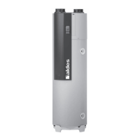
3.5.4. Condensate discharge
As the evaporator recovers the heat from the moist extract air, it causes condensation of the water vapour contained in the air.
This water, collected in a tray, is discharged using a 12 mm diameter clear pipe, supplied and fitted to the product.
Connect the discharge pipe to the wastewater ductwork with the accessory supplied (diaphragm adapter to
connect the condensate tube to a 32 mm diameter PVC pipe), taking care to provide for a flow water trap
and fill in with water (a diaphragm water trap can also be used that does not have to be filled with water).
Check the routing of the pipe once connected to avoid it catching anywhere.
Identical for T.Flow
®
Nano
3.6. Electrical connection
The thermodynamic water heater must have a constant supply to guarantee the production of DHW and the
operation of the titanium impressed current anode.
The thermodynamic water heater must not be electrically connected until it has been filled with water and the
ducts connected. Never supply the heating element directly with power.
The thermodynamic water heater power supply is single-phase current 230 V-50 Hz + Earth. It must be fitted by a professional
and comply with standard NF C 15-100 or the stipulations in force in the country where the water heater will be installed.
The electrical installation must include:
•
A 16 A omnipolar circuit breaker with at least 3 mm opening of contacts,
•
30 mA differential circuit breaker protection.
Connection terminals Power supply cables Circuit breaker protection
Permanent power supply
L,
, N
3G 1.5 mm
2
16 A
Off-peak power supply*(off-peak/peak) 4, 5 2G 1.5 mm
2
2 A
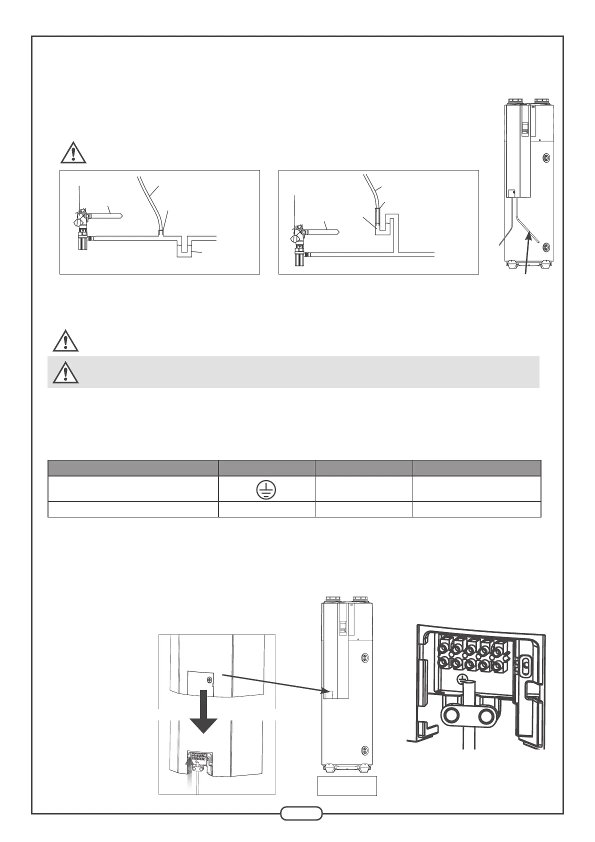
To create the electrical connection:
•
Remove the access hatch from the terminal block using a screwdriver,
•
Connect the electric cables to the terminal block according to the pricing structure (see next diagrams),
•
Reinsert the cable clamp (and screw in the hatch).
Identical for
T.Flow
®
Nano
Access hatch
Cable clamp
Front panel
Condensate tube: to be connected to the
wastewater flow water trap
Water trap
Mains water
inlet
Condensate pipe
Membrane union
Diagram 1
Safety switch
Wastewater outlet
(drains)
Water trap
Mains water
inlet
Safety switch
Condensate pipe
Membrane union
Diagram 2
Wastewater outlet
(drains)