18
AFTER SALES SUPPORT
support@scheppach.com.au
1300 855 831
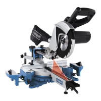
MODEL: HM80L PRODUCT CODE: 60120 04/2018
AUS Hotline Costs: Local rate for landline calls*
*Charges may vary dependent upon network operator or mobile network provider.
AUS
Before starting the equipment/Assembling and operation HM80L
VI. Before starting the equipment
• The equipment must be set up where it can stand securely, i.e. it should be bolt-
ed to a workbench, a universal base frame or similar. To do this, use the holes
located in the frame of the machine.
• All covers and safety devices have to be properly tted before the equipment is
switched on.
• It must be possible for the blade to run freely.
• When working with wood that has been processed before, watch out for foreign
bodies such as nails or screws, etc.
• Before you press the ON/OFF switch check that the saw blade is tted correct-
ly. Moving parts must run smoothly.
• Before you connect the equipment to the power supply make sure the data on
the rating plate are identical to the mains data.
VII. Assembling and operation
m Warning! Prior to any adjustment work disconnect the mains power plug!
7.1 Assembling (Fig. 1-4)
• To adjust the turntable rotate the turntable (15) and pointer (13) to the desired angle
on the scale (14).
• Pressing the machine head (5) lightly downwards and unlock the machine head
locking bolt (22) from the motor bracket at the same time disengages the saw from
the lowest position.
• Swing the machine head (5) up until the release lever (4) latches into place.
• It is possible to secure the clamping device (8) to the left or right on the machine
base (16). Long workpieces must be supported by the clamping device!
• Loosen the workpiece support cross-head screw (11) and push the workpiece sup-
port (9) all the way through the desired hole on the side of the machine base.
• Make sure that the workpiece support (9) is pushed through the two plates under-
neath the machine base.
• Re-tighten the workpiece support cross-head screw (11) and repeat this process on
the other side.
• Loosen the anti-tipper cross-head screw (34) and push the anti-tipper (10) through
the desired hole on the bottom side of the machine base.
• Re-tighten the anti-tipper cross-head screw (34) and repeat this process on the oth-
er side.
• It is possible to tilt the machine head (5) at max. 45° to the left by loosening the set
lever (21).