AFTER SALES SUPPORT
21
1300 855 831
support@scheppach.com.au
AUS Hotline Costs: Local rate for landline calls*
*Charges may vary dependent upon network operator or mobile network provider.
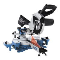
MODEL: HM80L PRODUCT CODE: 60120 04/2018
AUS
HM80L Assembling and operation
relation to the fence (double mitre cut).
Caution! To make mitre cuts (inclined saw head), the moveable fence (17a) must
be xed at the outer position.
• Open the set screw (17b) for the moveable fence (17a) and push the moveable
fence outwards.
• Warning! The moveable fence (17a) must be xed far enough in front of the in-
nermost position that the distance between the moveable fence (17a) and the
saw blade (7) amounts to a maximum of 8 mm.
• Before making a cut, check that the moveable fence (17a) and the saw blade (7)
cannot collide.
• Secure the set screw (17b) again.
• Move the machine head (5) to its upper position.
• Release the turntable (15) by loosening the turntable locking bolt (23).
• Set the turntable (15) to the desired angle (refer also to point 7.5 in this regard).
• Retighten the turntable locking bolt (23) in order to secure the turntable.
• Undo the set lever (21) and use the handle (2) to tilt the machine head (5) to the
left until it coincides with the required angle value (in this connection see also
section 7.6).
• Retighten the set lever (21).
• Cut as described under section 7.4.
7.8 Precision adjustment for crosscut 90° (Fig. 9)
90° angle gauge (a) not included.
• Lower the machine head (5) and secure it using the machine head locking bolt
(22).
• Loosen the set lever (21).
• Position the 90° angle gauge (a) between the saw blade (7) and the turntable
(15).
• Slacken the counter nut (e). Adjust the adjustment screw (24) until the angle be-
tween the saw blade (7) and turntable (15) is 90°.
• Retighten the counter nut (e) to secure this setting.
• Subsequently check the position of the angle indicator. If necessary loosen the
mitre cut pointer screw (g), set to position 0° on the mitre cut scale (19) and
retighten the mitre cut pointer screw (g).
7.9 Precision adjustment for mitre cut 45° (Fig. 10)
45° angle gauge (b) not included.
• Lower the machine head (5) and secure using the machine head locking bolt
(22).
• Fix the turntable (15) in the 0° position.
• Loosen the set lever (21) and use the handle (2) to angle the machine head (5)
45° to the left.
• Position the 45° angle gauge (b) between the saw blade (7) and turntable (15).