0 1 2 3 4 5 6 7 8 9
This document and it's contents are the exclusive property of Alfa Laval AB,
and may not be copied, reproduced, transmitted or communicated to a third party,
nor used for any pupose without written permission.
This document constitutes a contractual obligation on our
part only to the extent expressly agreed upon.
SETUAKL
Created by
SETUAKL
Revised by
Approved date
2015-10-23
Approved by
SETUNLNCAT
Department
2014-04-02
Created date
Document No.
9014734
Page Revision
Latest Revision
07
Project
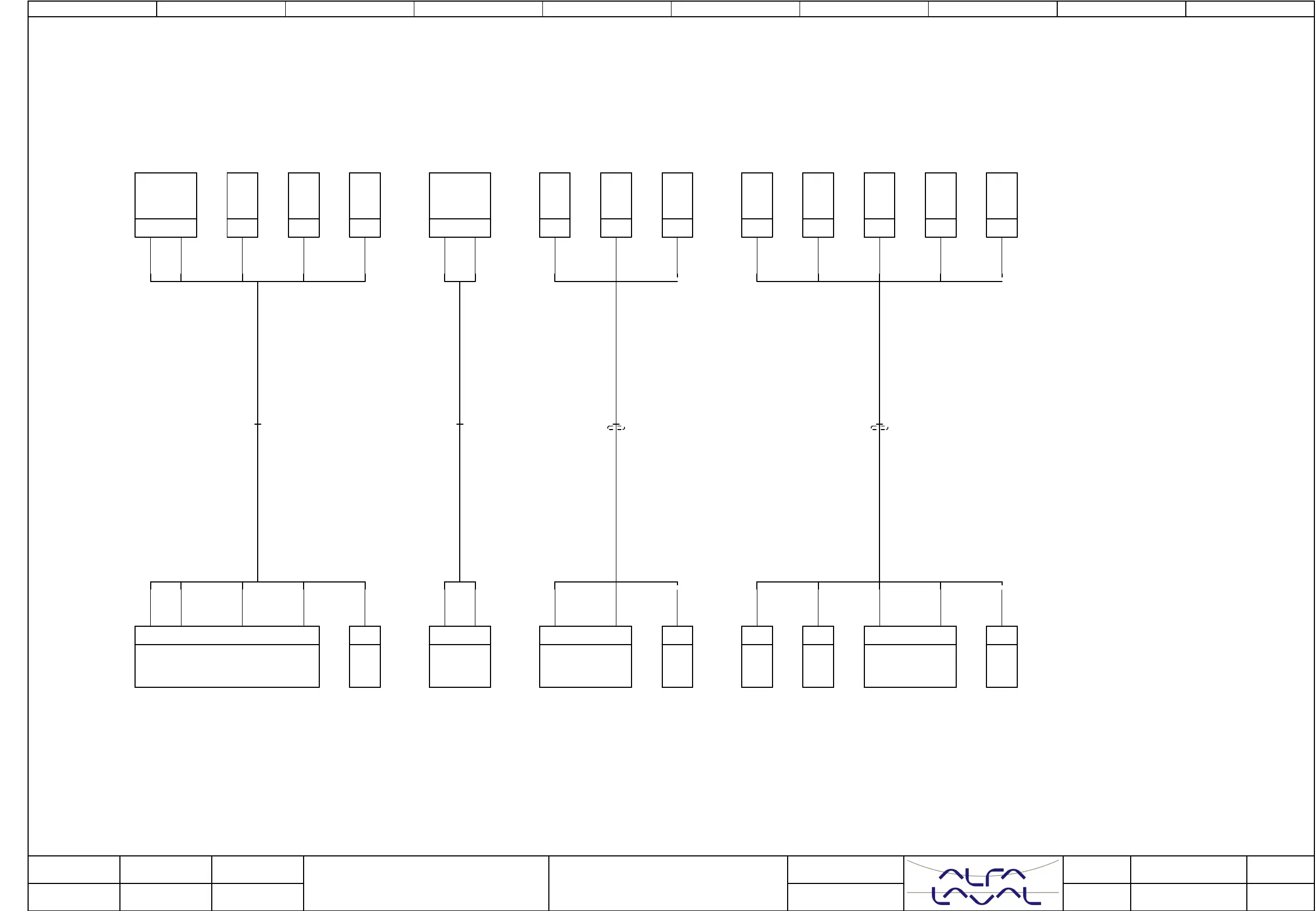
Cable-connection diagram W201
W202 W203 W401
Location
Mounting
Title
Emmie w. heater
Revised date
07 3
4
Next page
Page
2015-10-07
Internal targetsExternal targets
Shield SH shall be connected to cable glands,
except for power supply cables, they shall be connected to PE bar.
BNBN
Page.28/:271
BK-WHBK-WH
Page.28/:270
C
+Field
NC
-LS1
201
+CP01
X2
CNO
203
+CP01
BN
+Field
BUBU
Page.28/:274
204
X2
BU
-S1
Cover open
W202
22
Page.24/:233
202
+CP01
X2
34
+Field
-R1
Page.28/:271
Tank full
W201
GN-YEGN-YE
11
Page.21/:205
+
+CP01
X401
BNBN
Page.28/:274
SHSH
Page.24/:234
+CP01
SH
+Field
-SH
Oil
Overheat
W203
1BN1BN
Page.21/:205
+
+CP01
X401
1
+Field
-PT1-1
2WH2WH
Page.27/:265
402
+CP01
X4
BUBU
Page.28/:271
BKBK
Page.21/:204
+
+CP01
X401
3BU3BU
Page.21/:206
-
+CP01
X400
4BK4BK
Page.27/:265
401
+CP01
X4
43
+Field
-PT1-1
SHSH
Page.27/:265
+CP01
SH
+Field
-SH
Pressure
transmitter
W401