0 1 2 3 4 5 6 7 8 9
This document and it's contents are the exclusive property of Alfa Laval AB,
and may not be copied, reproduced, transmitted or communicated to a third party,
nor used for any pupose without written permission.
This document constitutes a contractual obligation on our
part only to the extent expressly agreed upon.
SETUTBL
Created by
SETUTBL
Revised by
Approved date
2015-10-23
Approved by
SETUNLNCAT
Department
2014-04-02
Created date
Document No.
9014734
Page Revision
Latest Revision
07
Project
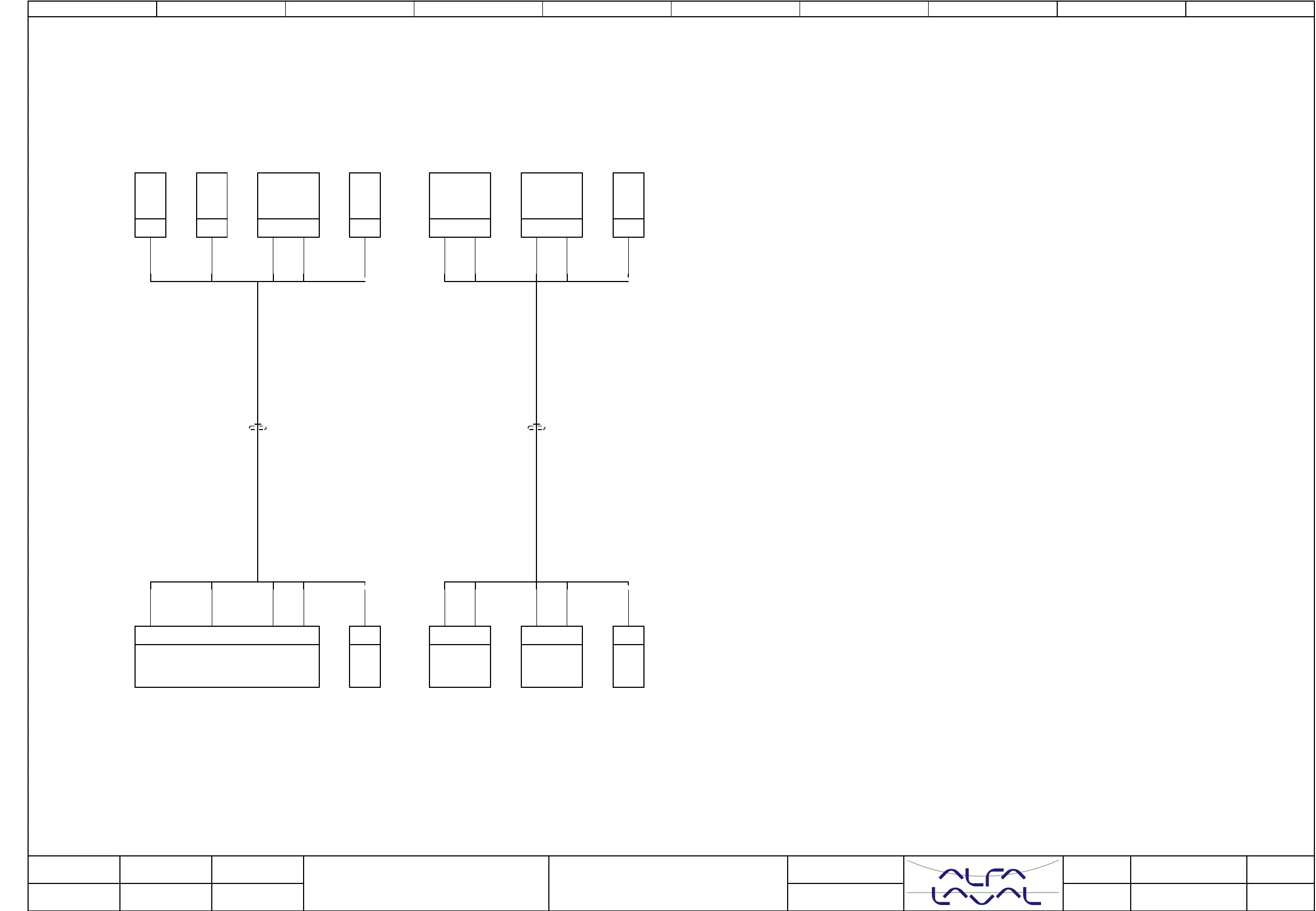
Cable-connection diagram W402
W403
Location
Mounting
Title
Emmie w. heater
Revised date
06 4
5
Next page
Page
2015-03-26
Internal targetsExternal targets
Shield SH shall be connected to cable glands,
except for power supply cables, they shall be connected to PE bar.
1BN1BN
Page.21/:205
+
+CP01
X401
3BU3BU
Page.27/:261
4BK4BK
Page.27/:261
Page.27/:261
+CP01
SH
+Field
-SH
Temperature
before separator
W403
SHSH
3BU3BU
Page.30/:292
1
+Field
4BK4BK
Page.30/:291
404403
+CP01
X4
432
-V1-1
2WH2WH
Page.21/:206
-
+CP01
X400
1BN1BN
Page.27/:260
2WH2WH
Page.27/:261
406405
+CP01
X4
21
+Field
-TT1
SHSH
Page.30/:292
+CP01
SH
+Field
-SH
Pressure
regulating valve
W402