6 Setup diagram
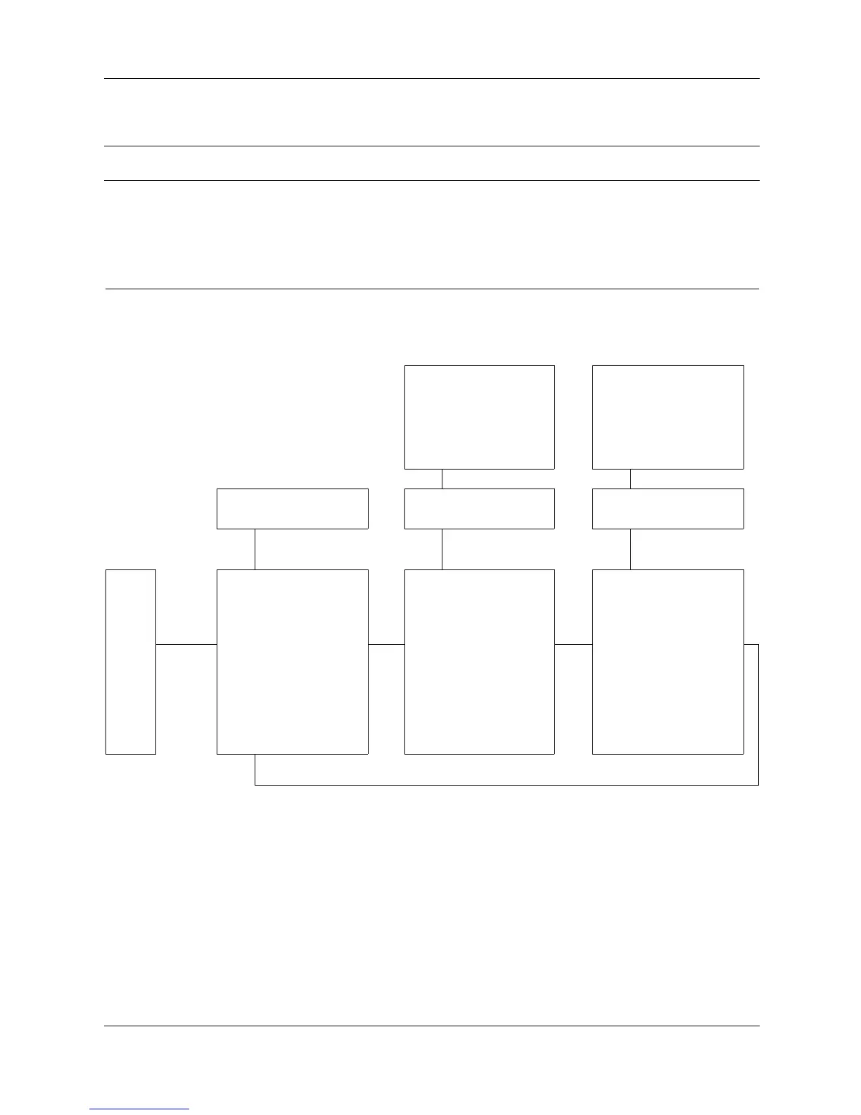
6.1 ThinkTop Basic AS-Interface setup
ThinkTop Basic Digital and AS-Interface
A printable “one page” version of ThinkTop Basic setup diagram is available on the Alfa Laval website and can easily be found
be typing the document name “ThinkTop Basic setup diagram” in the searh field.
Time-
out:
A 60 second time-out is started as soon as any
button(s) are released. If no button is pressed
during the time-out period, go to normal
condition (cancel & exit).
Red
LED:
Active during set-up
-Flashinginstep1
- Steady in all other steps
or during operations, error condition:
- Steady showing hardware fault,
indication pin out of range
- Flashing showing software fault
“red” steady “
green” flashing if
de-energized position
disabled “green” steady
if de-energized position
enabled
“red” steady
“yellow” flashing if energized
position disabled “yellow”
steady if energized position
enabled
“red” flashing
Actuator in De-energized
Position
Actuator in Energized
Position
Step 1 Step 2 Step 3
Accept Settings Set De-energized Position Set Energized Position
Next step
“I”
Restart set-up
sequence
Next
step
“II”
Store Position
Next
step
“II”
Store Position
“II”
Save & Exit
“I”
Bypass
“I”
Bypass
“II”*
Cancel & Exit, no
changes accepted
“II”* Disable function “II”* Disable function
Enter
set-up
“1”
* Hold for 5 sec. * Hold for 5 sec. * Hold for 5 sec.
Return to step 1
Quick set-up:
Push: “I”, enter setup and wait until red LED flashes.
Push: “I”, restart set-up.
Actuator in De-energized position
Push: “II”, store position
Actuator in energized position
Push: “II”, store position
Push: “II”, when red LED is flashing (save & exit)
Set-up done.
15