1. Sensor board
2. PLC, feedback
3. Sensor unit
4. PLC interface board
5. N/A
6. N/A
7. Serial link
8. LEDs
9. +5 V
10. Terminals
11. Terminals
12. ASI +
13. ASI -
14. Bus Connection
15. Internal connections
16. Solenoid signals (DC)
17. Solenoid common
18. N/A
19. N/A
20. N/A
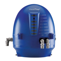
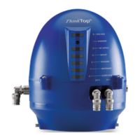
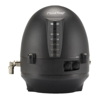
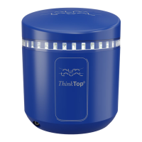
Type: Alfa Laval “No Touch” System. For wire connections: See 5.3 Electrical connection, internal“.
Features
- Easy and simple set-up, using locally pushbottons.
- No manual sensor adjustments at all.
- No sensor "movements" due to vibrations.
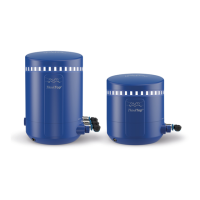
- Modular and hygienic design with exchangeabilities.
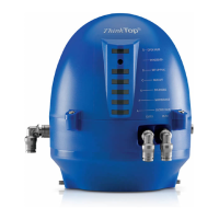
- Clear LED’s for visual status indication.
- Setup saved at power shutdown.
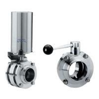
Sensor System
Unique “No Touch” sensor system without any mechanical sensor adjustments. A magnet (indication pin) is mounted on the
valve stem and the magnetic field (axial) is detected by sensor chips inside the sensor unit. The measuring angle from each
chip is used to locate the current position of the valve stem with an accuracy of ± 0.1mm. Note that the distance to the
indication pin can be 5 mm ± 3 mm.
Feedback signals
The sensor system can be used for 2 feedback signals.
Electrical connection
Direct main cable gland entry (hard wired) PG11 (ø4 - ø10 mm).
Te r mi na ls
The terminal row of the sensor board is equipped with screw terminals for both internal as well as external wires. The terminals
are suitable for wires up to 0.75 mm
2
(AWG 19).
7