Steps
1. Place the display assembly on the palm-rest and keyboard assembly.
CAUTION: To avoid damaging the display, do not slide display assembly over the palm-rest and keyboard assembly.
2. Align the screw holes on the display assembly with the screw holes on the palm-rest and keyboard assembly.
3. Replace the six screws (M2.5x5) that secure the display assembly to the palm-rest and keyboard assembly.
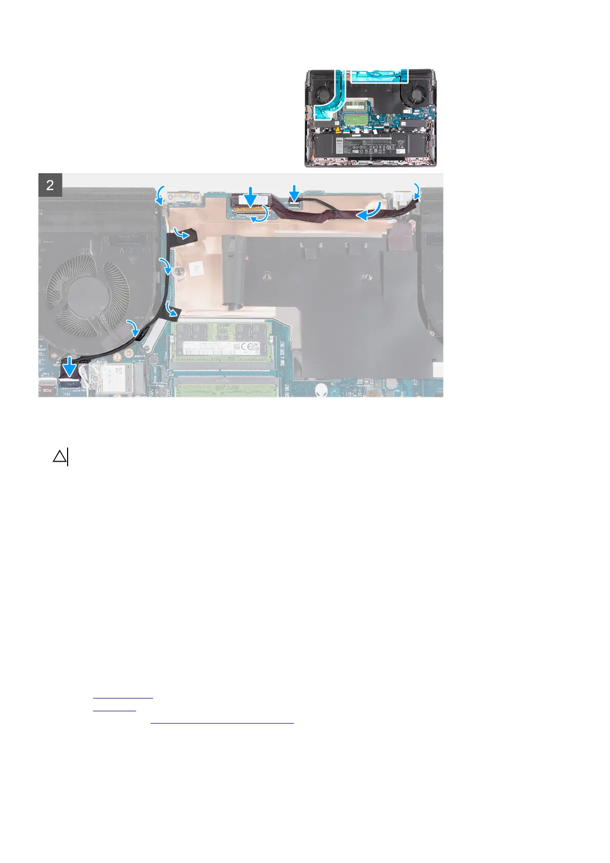
4. Route the display cable and Alien head LED-cable through the routing guides on the display assembly.
5. Turn over the computer.
6. Route the display cable through the slot on the palm-rest and keyboard assembly.
7. Connect the Alien head LED-cable to the system board.
8. Adhere the display cable to the system board.
9. Connect the display cable to the system board and close the latch to secure the cable.
10.Adhere the tape that secures the display-cable connector latch to the system board.
11. Adhere the tapes that secure the camera cable to the system board.
12. Route the camera cable through the slot on the palm-rest and keyboard assembly.
13. Route the camera cable through the routing guides on the palm-rest and keyboard assembly and fan.
14. Connect the camera cable to the system board.
Next steps
1. Install the
rear-I/O cover.
2. Install the
base cover.
3. Follow the procedure in After working inside your computer.
48