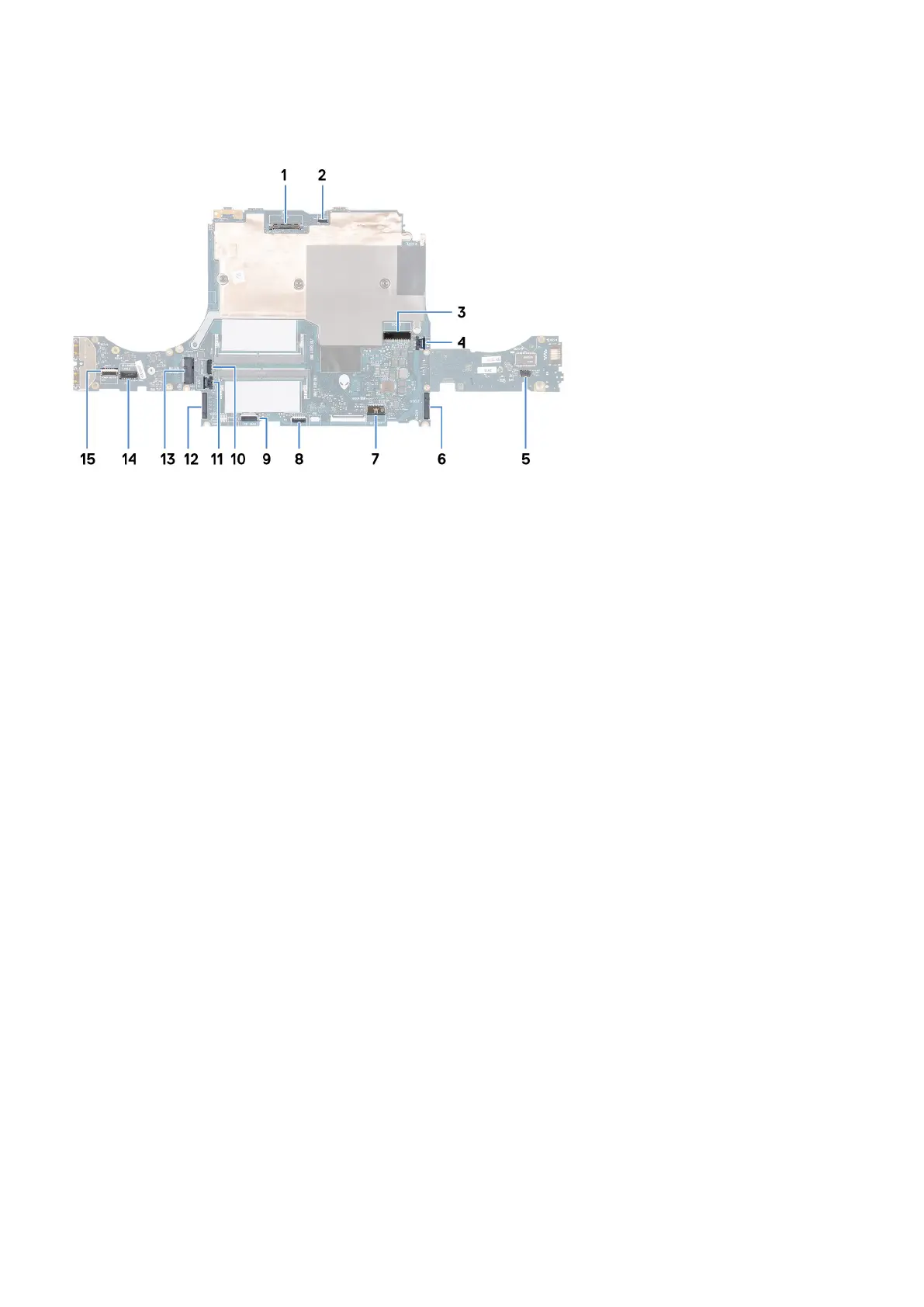
About this task
The following image indicates the connectors on your system board.
1. Display cable
2. Alien head LED-cable
3. Power-adapter port cable
4. Right-fan cable
5. Speaker cable
6. M.2 card slot for solid-state drive 2
7. Battery cable
8. Touchpad connector
9. Keyboard-controller board cable
10.Tron-light cable
11. Left-fan cable
12. M.2 card slot for solid-state drive 1
13. Wireless-card slot
14. Camera cable
15.Power-button cable
The following image(s) indicate the location of the system board and provides a visual representation of the installation procedure.
54