Steps
1. Remove the two screws (M1.6x1.8) that secure the display-cable bracket to the system board and palm-rest and keyboard
assembly.
2. Remove the display-cable bracket off the system board and palm-rest and keyboard assembly.
3. Disconnect the display cable from the system board.
4. Peel the Mylar that secures the I/O-board cable to the system board.
5. Open the latch and disconnect the I/O-board cable from the system board.
6. Open the latch and disconnect the right-fan cable from the system board.
7. Open the latch and disconnect the keyboard-controller board cable from the system board.
8. Disconnect the speaker cable from the system board.
9. Open the latch and disconnect the power-button cable from the system board.
10.Open the latch and disconnect the left-fan cable from the system board.
11. Peel the tape that secures the headset port cable to the system board.
12. Open the latch and disconnect the headset port cable from the system board and remove it from the routing guides on the fan
and heat-sink assembly.
13. Remove the nine screws (M2x4) that secure the system-board assembly to the palm-rest and keyboard assembly.
14. Grab the system-board assembly from the top left and right sides of the heat sink and lift the system-board assembly off the
palm-rest and keyboard assembly.
15.Place the system-board assembly on a clean and flat surface.
16.Turn the system-board assembly over.
17. Remove the
fan and heat-sink assembly.
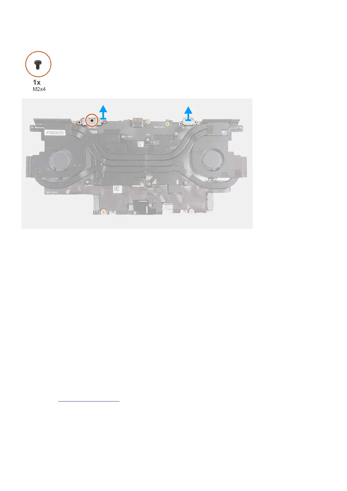
18.Remove the screw (M2x4) that secures the USB Type-C bracket to the system board.
19.Lift the left USB Type-C bracket off the system board.
20.Lift the right USB Type-C bracket off the system board.
21. Turn the system-board assembly over.
22.After performing all the steps, you are left with the system board.
44