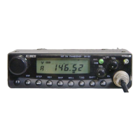
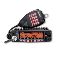
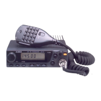
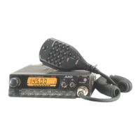
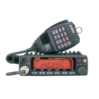
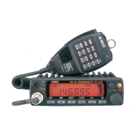
D R - 1 5 0 T / E
S e r v i c e M a n u a l
CONTENTS
• SPECIFICATIONS
1) General
............................................................2
2) Transmitter.......................................................2
3) Receiver...........................................................2
• CIRCUIT DESCRIPTION
1) Receiver System.............................................. 3
2) Transmitter System......................................3 -4
3) PLL Circuit........................................................ 4
4) Terminal Function of Microprocessor
..........
5 - 7
5) Terminal Function of 4094
................................
8
• SEMICONDUCTOR DATA
1) AT24C08-10SI-2.7
............................................
9
2) BU4094BF........................................................9
3) MB1504LPF-G-BND-TF
..................................
10
4) NJM2902M (T1)
..............................................
10
5) NJM7809A
......................................................11
6) RH5VA45AA-T1.............................................. 11
7) TA75S01F.......................................................11
8) TA7806F (TE16L)
...........................................
11
9) S-AV17
............................................................12
10) TC35305F (TP1)............................................. 13
11) TK10930VTL...................................................14
12) TC4W66FU......................................................15
13) nPC1241H....................................................... 15
14) Transistor, Diode and LED Outline Drawings....16
15) LCD Connection............................................. 17
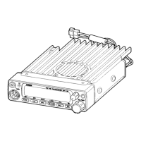
• EXPLODED VIEW
1) Bottom View....................................................18
2) LCD View........................................................18
3) Top, Front View............................................... 19
• PARTS LIST
CPU Unit................................................. 20-21
MAIN Unit................................................22-25
VCO Unit.........................................................26
SPUnit............................................................26
MIC Unit..........................................................27
Mechanical Parts............................................27
Others.............................................................28
Packing............................................................28
Mic. Hanger Unit.............................................. 28
EJ20u..............................................................28
• ADJUSTMENT
1) Required Test Equipment
...............................
29
2) Adjustment for DR-150T/E
..............................
30
3) Adjustment Points
...........................................
31
4) Adjustment Quick Reference
...........................
31
• VOLTAGE TABLE
1) Transistor, FET
................................................32
2) Diode...............................................................33
3) Connector........................................................33
4) IC.....................................................................34
• PC BOARD VIEW
1) MIC Unit Side A............................................... 35
2) MIC Unit Side B...............................................35
3) VCO Unit Side A.............................................35
4) CPU Unit Side A.............................................. 36
5) CPU Unit Side
B
............................................. 36
6)
MAIN Unit Side A............................................ 3
7
7) MAIN Unit Side B............................................38
• BLOCK DIAGRAM....................................................39
• CIRCUIT DIAGRAM
1) MIC Unit...........................................................40
2) VCO Unit.........................................................41
3) Main Unit.........................................................42
4) CPU Unit.........................................................44
5) EJ20u Unit....................................................... 45
A U N C O , Inc