13
1. Rinse the chemical line by inserting the screen into
a container of clear water and open the metering
valve 1 minute to clean it of any remaining residue.
Be sure the chemical metering valve is closed when
finished.
2. Check the position of the ball valve (if so equipped)
on the outlet of the float tank assuring it is in the
closed position.
3. Attach an air chuck to the air valve stem on the
pump assembly. With the trigger gun in the open
position, apply air until a mixture of air and very
little water is coming from the gun wand Then turn
switch to the “BURNER” position and depress the
vacuum switch. Run it for 45 seconds allowing any
remaining water to turn to steam. Allow air to blow
for 60 seconds. Turn switch to the “OFF” position.
4. Remove the air chuck.
5. Fill a 1-gallon container with Ethylene Glycol type
antifreeze. Minimum should be a mixture of ½
antifreeze and ½ water strength before each use,
as the antifreeze will dilute with use.
6. FLOAT TANK EQUIPPED: Pour the anti-freeze
solution into the float tank.
7. WITHOUT FLOAT TANK: Install a 2-ft. Garden hose
to the water inlet. Insert the other end into a
container of antifreeze solution.
8. Turn on the switch to the “PUMP” position.
9. Turn off the switch just prior to running out of
antifreeze mixture.
10. Disconnect electrical supply.
11 Fill the fuel tank with kerosene or #1 or #2 diesel.
12 It is recommended to install a coil cover to keep
coil free of debris
13 Drain the float tank.
14 Place machine in a dry place protected from weather
condition.
PART NO. DESCRIPTION
Y02-00001 …….....0-1000 PSI (69 BAR) Pressure Gauge
NOTE: All Gauges are Glycerin Filled ¼ NPT
Z01-00070-1…….3/8” x 100 Yards Thread Tape
1. Connect machine to an electrically grounded
circuit that is fuse or circuit breaker protected.
2. Connect machine to a pressurized water supply
meeting the requirements specified in the GENERAL
section of the MODEL SPECIFICATIONS.
3. Turn on the water supply.
4. Check the float tank (if so equipped) to assure it is
full and the float valve shuts off securely.
5. Check the position of the ball valve (if so equipped)
on outlet line of the float tank assuring it is in the
open position.
6. Remove spray tip from gun assembly.
7. With the gun assembly in hand (on trigger gun
models hold the trigger gun valve in open position)
and with a good flow of water turn switch to the
PUMP position
CAUTION: A good flow of water must be flowing
from the end of a gun within 30 seconds, before
proceeding. Lack of water can cause water pump
damage.
CAUTION: DO NOT RUN PUMP WITHOUT WATER,
AS THIS WILL CAUSE DAMAGE TO THE PUMP
AND VOID WARRANTY.
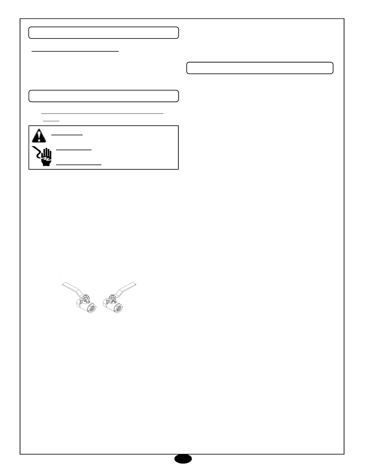
OPEN
CLOSED
BALL VALVE POSITION
x
06-21-06 Z08-02810
ACCESSORIES
FLUSHING
STORAGE
WARNING: ELECTRICAL SHOCK HAZARD
LE DANGER ELECTRIQUE DE CHOC
ADVERTENCIA: CHOQUE ELÉCTRICO
CAUTION: On a machine equipped with a trigger
gun valve, if the trigger gun valve remains in the
closed position for more than 5 minutes, water pump
damage may occur.
Supersedes 08-15-03 Z08-02810