ALL-TEST PRO
®
31 User Manual
©2011, ALL-TEST Pro, LLC www.alltestpro.com rev 2011-11F 12
Note: For quick trouble shooting the order of the readings is not important. However, for long
term trending of the data, testing should be performed in the same order each time.
Optional: Connect the Yellow lead to ground, this is only required for measuring insulation to ground.
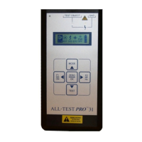
Turn the Instrument On
Press and hold the F1/ON key for 1 to 3 seconds. This will bring up the main display screen.
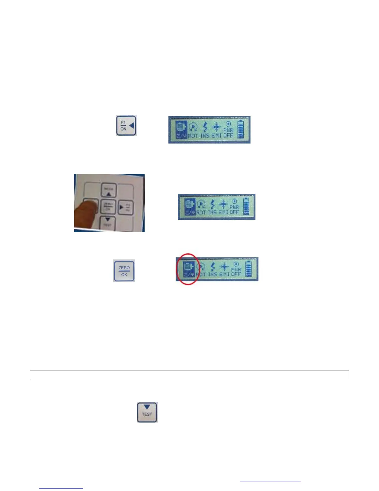
Select the Motor Test
1. Using the ◄ F1 and ► F2, keys highlight the Winding Test icon
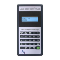
2. Press the ZERO/OK Key to select the Winding Test icon (Z/ψ) from the main menu.
Observe/Record the Test Data
1. The default value is 200 Hz, as displayed in the bottom right corner of the display screen.
a. The value of the impedance should be between 1 and 999 Ω. If the Z is less than 1 or
greater than 999 Ω change the test frequency of the winding test (see Changing the
Motor Test Frequency on page 24).
b. The current frequency response value (I/F) must be between -15 and -50, if it is not
change the frequency of the winding test.
c. If the phase angle (Fi) is less than 15
°
, change the winding test frequency.
Note: If any of the measurements fall outside the above ranges, the test is not valid.
2. Display screen 2 displays the results of the current frequency test. To view display screen 2
Press the TEST key.