ALL-TEST PRO
®
31 User Manual
©2011, ALL-TEST Pro, LLC www.alltestpro.com rev 2011-11F 7
III. ALL-TEST PRO® 31 Kit Components
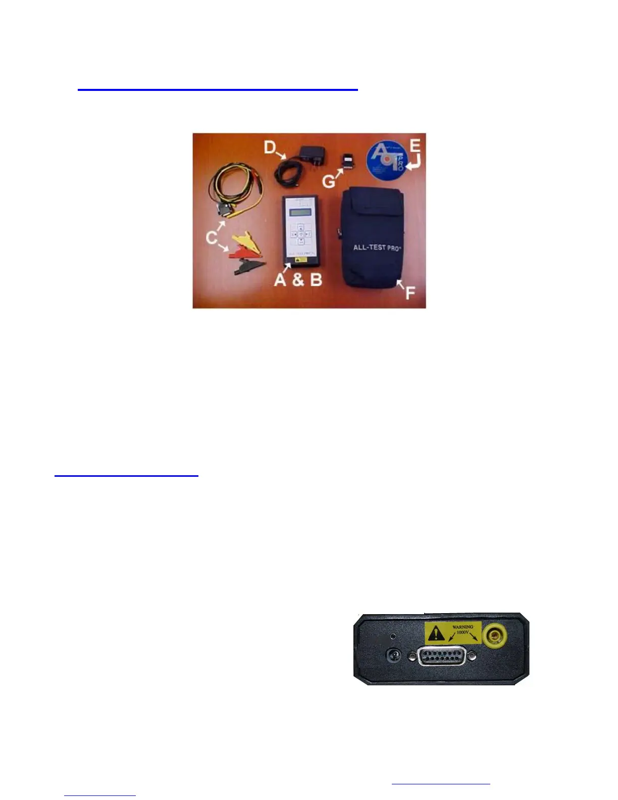
Figure 1: AT 31 Kit
The AT31 Kit contains all of the necessary components necessary to test most electrical machinery:
A. ALL-TEST PRO® 31 instrument
B. Batteries (installed)
C. Test leads and clips
D. Charger (115 or 230 Volt)
E. Manual on CD Rom
F. Carrying Pouch
G. Reset Key (Only sent with units before Serial number 2029)
Instrument Operation
The instrument is divided up into three working areas:
1. Input Section
2. Display Area
3. Keypad
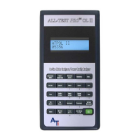
Input Section
The input section provides all the external connections to the ALL-TEST PRO® 31
A. Test lead port
B. Charger port
C. Ground test lead port for Insulation to Ground
Measurements
D. Reset Button (Serial number 2029 and higher)
A B
C
D