Do you have a question about the ALL-TEST PRO AT31 and is the answer not in the manual?
Lists all necessary components included in the AT31 kit for electrical machinery testing.
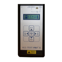
Describes the instrument's division into Input, Display, and Keypad sections for user interaction.
Details the external connections and ports available on the ALL-TEST PRO® 31 instrument.
Covers the instrument's display features including indicator lights and screen layout.
Explains display icons and the functions of the instrument's keypad.
Details keypad usage and proper connection of test leads.
Introduces testing procedures and lists the required equipment for three-phase motors.
Step-by-step guide for performing the winding test on three-phase motors.
How to turn on the AT31 and select the desired motor test from the main menu.
Provides default frequencies and acceptable ranges for impedance, I/F, and phase angle.
Details the information presented on Display Screen 1 and Display Screen 2.
Explains the meaning of E1 and E2 error codes displayed on the instrument.
Procedure for connecting leads and taking measurements for the second phase.
Procedure for connecting leads and taking measurements for the third phase.
Instructions on how to record impedance, phase angle, and I/F values on the test form.
Explains the function of phase balance testing and the Impedance Unbalance Calculator.
Initial steps for setting the reference phase for impedance unbalance measurement.
Procedures for obtaining maximum impedance and setting the reference phase to zero.
Steps for measuring and recording phase balance/unbalance values for all phases.
Guidelines for interpreting phase balance readings and identifying potential faults.
Explains the safety purpose and provides voltage tables for insulation resistance tests.
Steps to navigate, connect leads, and initiate the insulation resistance test.
How to toggle voltage and verify test lead connection to ground.
Steps for performing the insulation resistance test and recording results.
Explains the principle of rotor testing and introduces Bar Test and Waveform Test.
Initial steps for powering on, connecting leads, and selecting the rotor test.
Steps for running the test, turning the shaft, and interpreting results via value/bar methods.
Procedure for performing the waveform test and adjusting shaft speed for optimal display.
How to interpret symmetrical, repeating waveforms versus non-repeating or flat peaks.
Steps to safely turn off the ALL-TEST PRO® 31 instrument.
Explains when and how to change the test frequency for optimal measurements.
Detailed steps for selecting the winding test and cycling through available frequencies.
Defines EMI, its sources, effects, and importance in test accuracy.
Discusses facts about EMI and how to identify and address interference issues.
Step-by-step instructions for performing the EMI test on the instrument.
Methods for resetting the unit using a reset key or internal button.
Instructions for using the internal reset button for units with serial numbers 2029 and above.
Recommendations for battery care, charge duration, and trickle charging.
Steps for connecting the charger to the unit and power source.
Explains the meaning of the red and green charging indicator lights.
General advice on interpreting test results and considering application specifics.
Table summarizing pass/fail criteria for Impedance, Phase Angle, I/F, and Phase Balance.
Table detailing insulation resistance values based on motor voltage rating.
Key factors like test location, rotor windings, and confirming faults for accurate interpretation.
Importance of confirming test location if faults are detected remotely.
How to determine if a fault is in the rotor or stator by rotating the shaft.
Guidelines for identifying winding shorts using frequency and unbalance indicators.
Detailed steps for performing a rotor compensation test to isolate faults.
Procedure for using variable frequencies to confirm winding faults when readings are balanced.
Introduction to limited troubleshooting capabilities for DC motors with the AT31.
Specific procedures for testing the field of series DC motors.
Procedures for testing the field of shunt and compound DC motors.
Lists the three basic methods for testing DC armatures: Trending, Assembled, Disassembled.
Detailed steps for testing assembled DC armatures with brushes lifted.
Steps for testing disassembled DC armatures using specialized forks.
Methods for analyzing DC field coil and armature performance.
Procedures for testing stator and rotor coils separately in wound rotor motors.
Connection sequence and testing considerations for Wye-Delta motors.
Step-by-step guide for performing pass/fail tests on motor capacitors.
Contact details for obtaining technical assistance and support.
Lists optional accessories and software available for the ALL-TEST PRO® 31.
Details about the Motor Diagnostics Workshop and contact information for enrollment.
| Category | Measuring Instruments |
|---|---|
| Voltage Range | 600 V AC/DC |
| Temperature Range | -20°C to 60°C |
| Display | LCD |
| Connectivity | USB |
| Model | ALL-TEST PRO AT31 |