4 Connecting the controller
© 2021 Interflex Datensysteme GmbH IF-4070 Controller 14
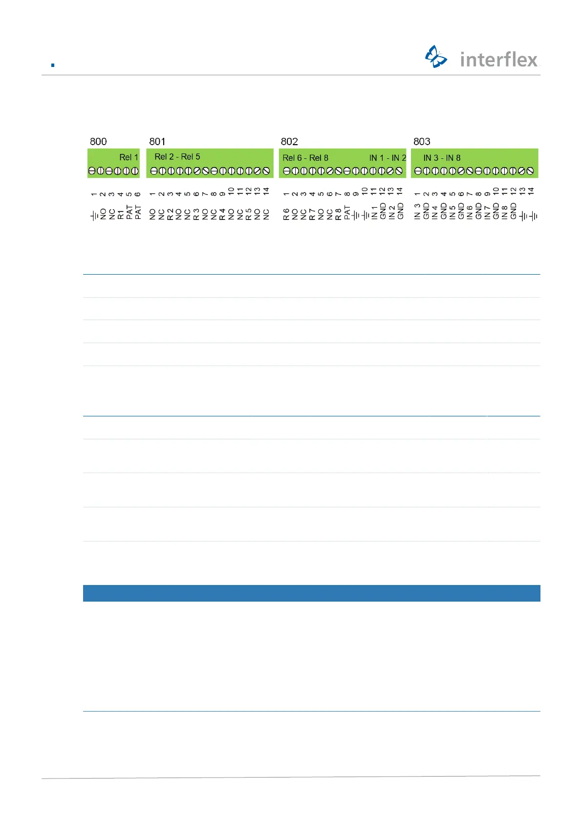
Screw terminals overview
Screw terminals for floating status contacts
802 803
Input 1 Input 2 Input 3 Input 4 Input 5 Input 6 Input 7 Input 8
11 IN 1 13 IN 2 1 IN 3 3 IN 4 5 IN 5 7 IN 6 9 IN 7 11 IN 8
12 GND 14 GND 2 GND 4 GND 6 GND 8 GND 10 GND 12 GND
Cable shield 10 Cable shield 13 or 14
Screw terminals for relays
800 801 802
Relay 1 Relay 2 Relay 3 Relay 4 Relay 5 Relay 6 Relay 7 Relay 8
2 NO
contacts
1 NO
contacts
4 NO
contacts
7 NO
contacts
10 NO
contacts
13 NO
contacts
2 NO
contacts
5 NO
contacts
3 NC
contacts
2 NC
contacts
5 NC
contacts
8 NC
contacts
11 NC
contacts
14 NC
contacts
3 NC
contacts
6 NC
contacts
4 R1 3 R2 6 R3 9 R4 12 R5 1 R6
(on 802)
4 R7 7 R8
4.3 Connecting the power supply
NOTICE
Malfunction due to improper electrical installation
Improper electrical installation can lead to malfunctions in operation and equipment failures. Therefore,
please note the following:
u Use shielded cables Cable lengths and cable types [}5]
u Ground the shields on the devices and cables
u Provide power to actuators (e.g., door openers) separately from terminals/controllers
u Use mains filter
 Loading...