3–7Configuration and Interfacing
Publication 1203–5.1 –– July, 1997
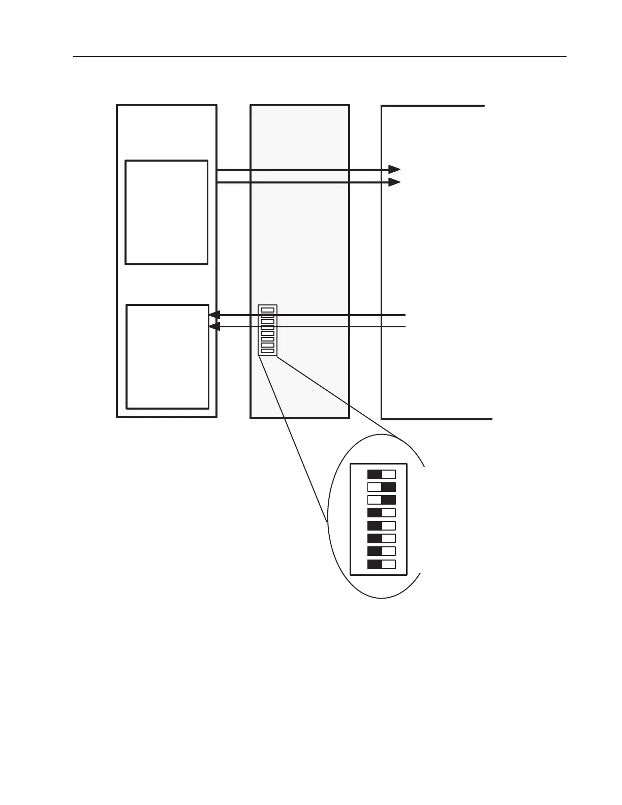
Figure 3.5
Typical Programmable Controller Configuration for SMP3
Output Image
Logic Command
WORD 1 REF
WORD 2
WORD 3
WORD 4
WORD 5
WORD 6
WORD 7
Remote I/O
Communications
Module
Input Image
SW3
SMP3Programmable
Controller I/O
Image Table
Logic Status
Feedback
WORD 2
WORD 3
WORD 4
WORD 5
WORD 6
WORD 7
SW3
12345678
OPEN
Datalink B Off
Datalink C Off
Datalink D Off
Truncate Last Datalink Off
Datalink A Off
Feedback On
Logic Cmd/Sts On
Block Transfer Off
AB0507A
*NOTE: While the reference is sent via the SCANport
to the SMP3, the reference is ignored by the SMP3.

 Loading...