8 POINT I/O 4 Channel IO-Link Master Module
Publication 1734-IN043A-EN-E - September 2015
Install the Module
The module can be installed before or after base installation. Make sure that the mounting
base is correctly keyed before installing the module into the mounting base. In addition,
make sure the mounting base locking screw is positioned horizontal referenced to the base.
1. Using a bladed screwdriver, rotate the keyswitch on the mounting base clockwise
until the number required for the type of module being installed aligns with the
notch in the base.
2. Make certain the DIN rail locking screw is in the horizontal position. You cannot
insert the module if the locking mechanism is unlocked.
3. Insert the module straight down into the mounting base.
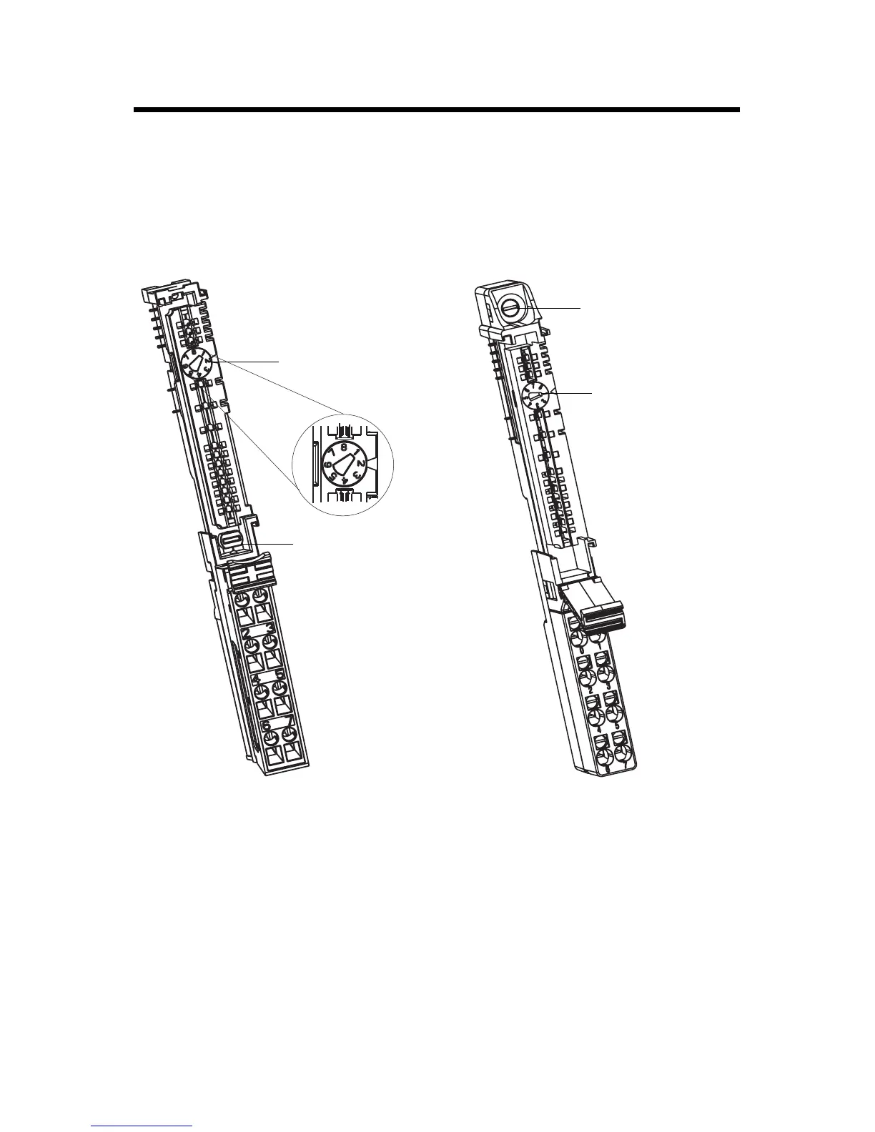
Turn the keyswitch to
align the number with
the notch. Notch
position 2 is shown.
Be sure the DIN-rail
locking screw is in the
horizontal position.
1734-TB Base
44229
Turn the keyswitch
to align the number
with the notch.
Notch position 2 is
shown.
Be sure the DIN-rail
locking screw is in the
horizontal position.
1734-TOP Base
44228

 Loading...

